This major project had to be completed in stages in order to prevent any disruption of shipping. A diversion channel had to be built in the Cornwall Canal between locks 19 and 20 to bypass the site of the new Moses-Saunders power dam. This also provided the location of the gate in the dike which would be closed the day before the flooding took place. Temporary dikes and cofferdams had to be built to divert or stop water flow through areas of the construction sites. |
A new control dam from the New York State mainland to Barnhart Island was built in stages in order to maintain flow down the river. Cuts through Long Sault Island were necessary for water diversion and a new shipping channel. Two new lift locks were built on the U.S. side of the river. A 10 mile shipping channel connecting the new lake was created above the dams to the river and below the city of Cornwall. Dikes were built on both sides of the river to control flooding inland once the new Lake St. Lawrence was created. |
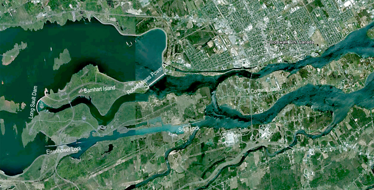
SHCMS000: Google Map of the Cornwall-Massena Section of the Seaway Today
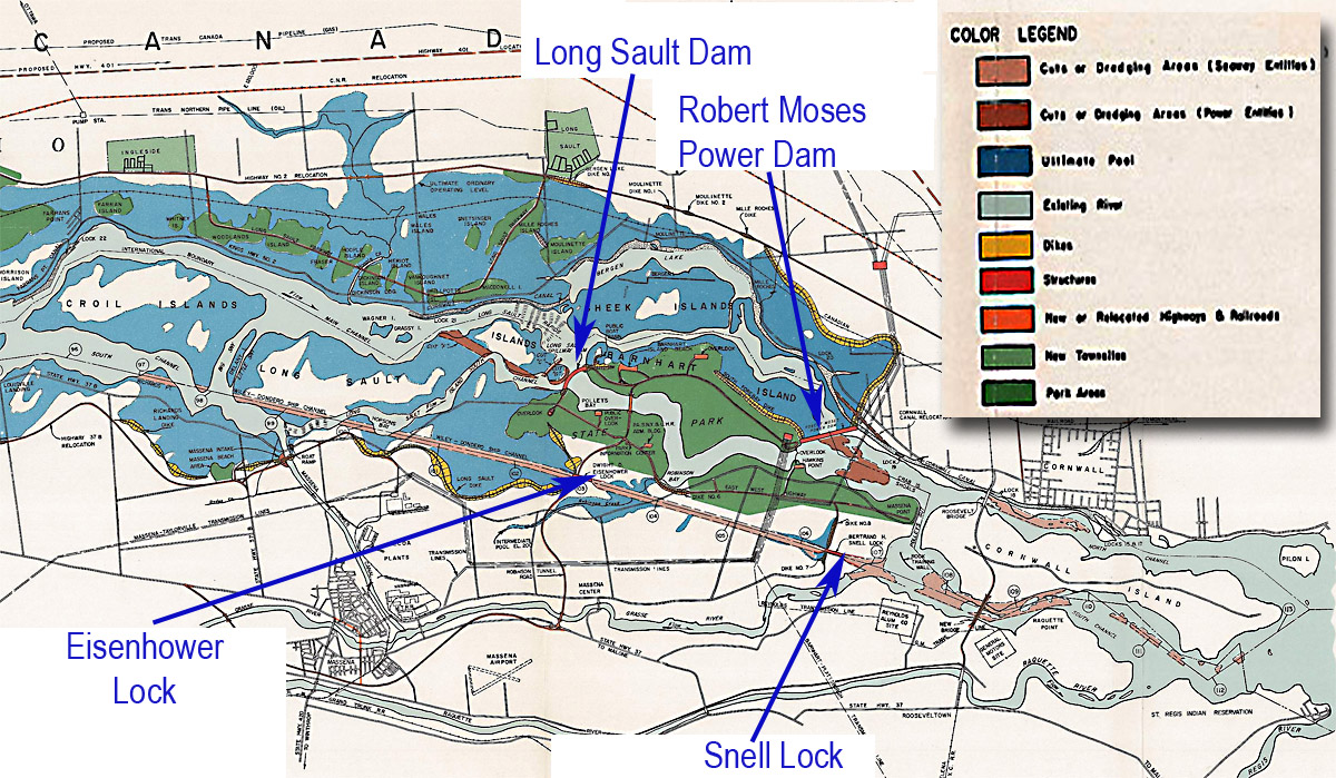
SHCMS000a: Ontario Hydro Blueprint for Cornwall-Massena Section of the Seaway
July 1958
This map is the Ontario Hydro Blueprint plan for the Cornwall-Massena section of the Seaway. It shows the original river boundaries (light blue), the flooded areas (dark blue) and the cuts/dredging areas (light & dark brown). The new Eisenhower & Snell Locks are marked with the Long Sault & Robert Moses Dams.
To see the complete Ontario Hydro Blueprint (from Prescott to Cornwall):- Click Here.

SHCMS000b: Map of the Cornwall Massena dam and canal construction site in 1957.
This map was drawn at a time when the south half of the Barnhart Island Control Dam has been completed and the flow of the river has been diverted through a cut F, which divided Long Sault Island into two islands. Four cofferdams had to be built to facilitate this stage of the Control Dam and Power Dam construction. They were given designated letters.
Coffer Dam E was built close to Lock 21 at Dickinson's Landing. The other cofferdams were built at the following locations. The Long Sault Cofferdam was built from the eastern tip of Long Sault Island to the north end of the new Barnhart Island Control Dam. From there it was extended to reach the west tip of Barnhart Island. There was another cofferdam built between the north shore of Barnhart Island across the bed of the Long Sault Rapids to Sheek Island.
Down stream from there the site of the Moses Saunders Power Dam had to be isolated from the river with a huge steel cofferdam right across the east side of this site. All of these dams enabled construction to take place 'in the dry.'
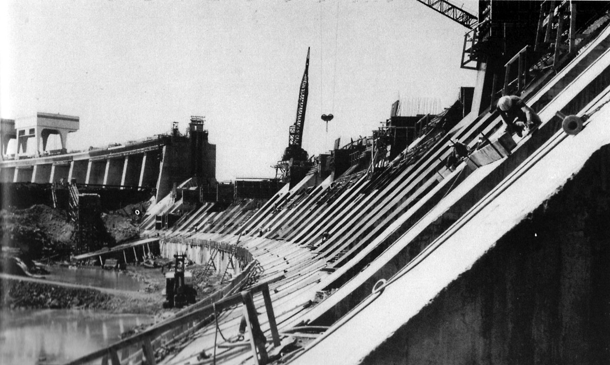
SHCMS001: Barnhart Island (Long Sault) Dam
Looking northwest from the New York State mainland at the southern half of the Barnhart Island Dam. The location is a short distance below the eastern tip of Long Sault Island and right across the rapids from Barnhart Island. The new dam is being built inside a cofferdam. The bridge on the right is for the next stage of construction of the dam. The work began on this site in August of 1954. The Moses Saunders power dam site is located to the north of this site and 3.5 miles down stream.
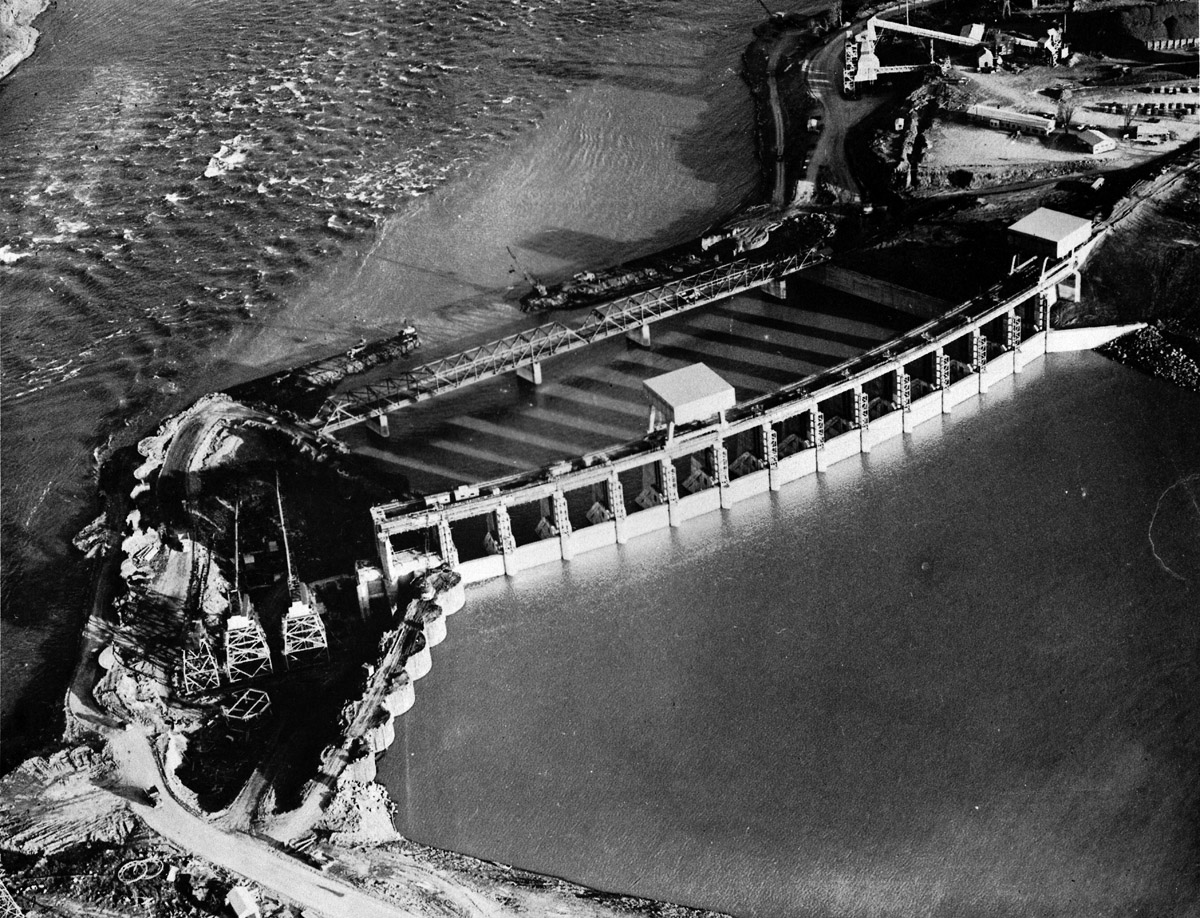
SHCMS002: Barnhart Island Control Dam
Looking about due north at the first phase of the Barnhart Island Control Dam which is nearing completion. The temporary dike located west of the dam is breeched and water is allowed to flood the front of the dam. Cranes are at work disassembling the sheet piling cofferdam below the control dam. This dam is 114 feet high from foundation to the top of the structure.
SHCMS002a: Barnhart Island Control Dam
The lower cofferdam below the control dam is now breeched and the bridge is now in use for all traffic to and from the northern section of the site. Soon the gates of the new southern section of the dam will be opened to allow all flow of the river through.
SHCMS003: Barnhart Island Control Dam
The foundations for the northern half of the Barnhart Island Dam are in place and concrete is being poured into the forms around the clock.
Total concrete poured: 750,000 cubic yards for the entire dam. Total reinforcing steel: 9,313,000 pounds. Total structural steel: 4.2 million pounds. Contract amount: $25,780,911.
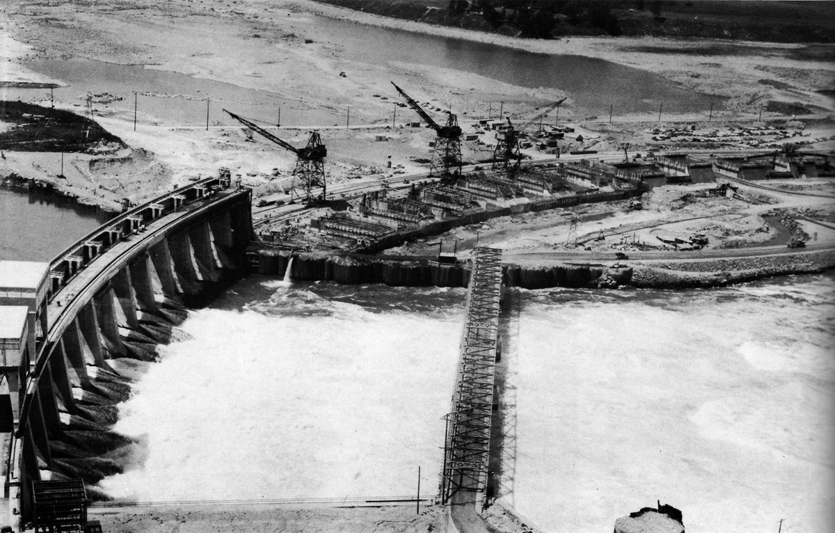
SHCMS004: Barnhart Island Control Dam
Looking northwest over the site of the Barnhart Island Dam. Note the rapids have gone dry above the north section of the dam. A temporary dike was built right across the Long Sault Rapids so that construction could begin to build the Moses Saunders Power Dam. A cut was dug through the middle of Long Sault Island to divert water from the Rapids to the southern half of the Barnhart Island Dam
SHCMS005: Barnhart Island Control Dam
The northern half of the dam rises up from the footings as forms are filled with reinforcing steel and concrete.
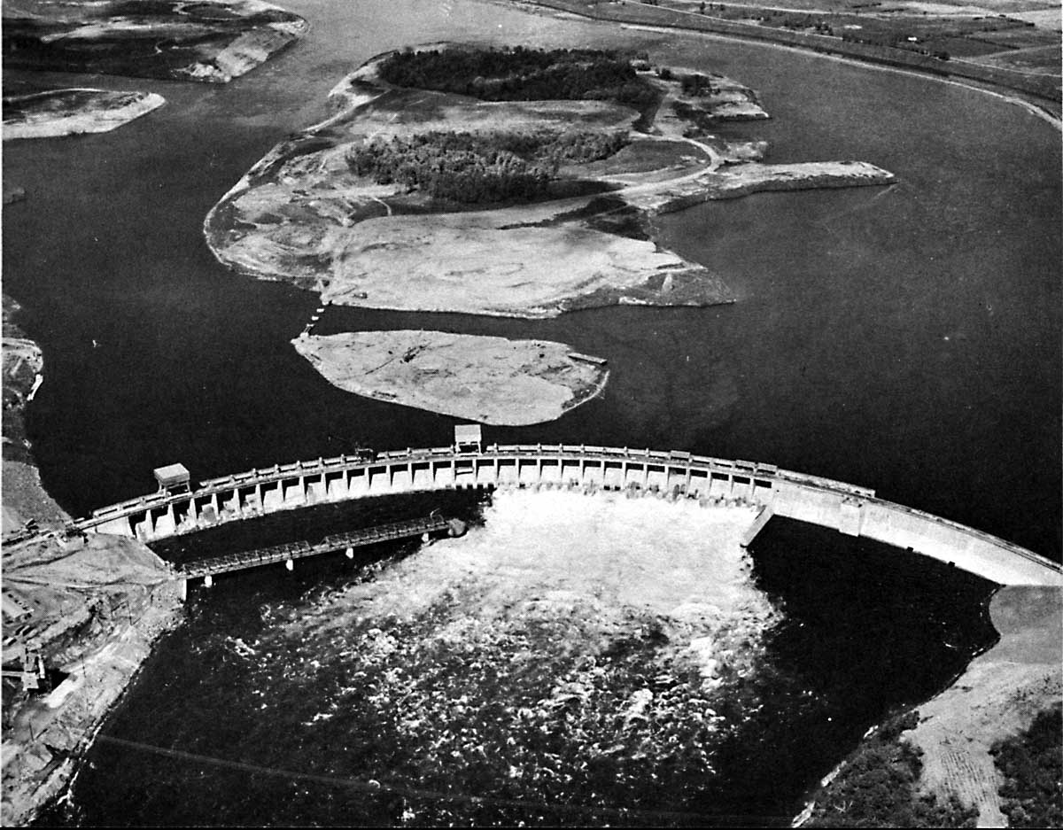
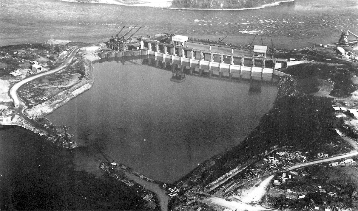
SHCMS005a: Barnhart Island Control Dam.
This aerial view of the completed Barnhart Island Control Dam was taken just before the flooding was to begin to create Lake St. Lawrence. Long Sault Island is in the center of the photograph. Only the areas not to be covered with water still have trees standing.
The former site of the Long Sault Rapids is to the right of the Island. The cofferdam, which dried up the Long Sault Rapids while the dams were being built, is now gone. It ran from Long Sault Island to the canal bank seen at the top of this image. The diversion channel, or "Cut F", is at the top left of the island. This cut was made to maintain proper water level at the entrance to the Cornwall Canalat Dikinson's Landing while the coffer dam was in place.
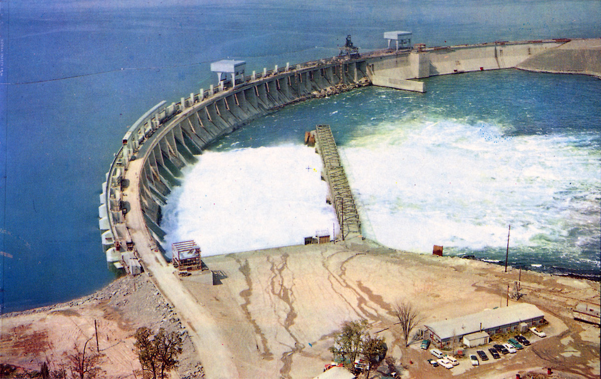
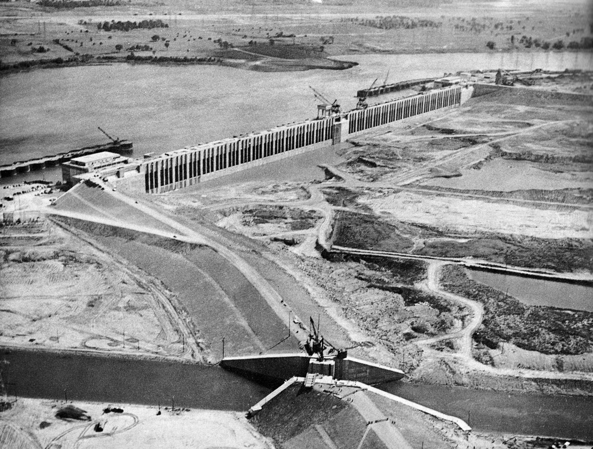
SHCMS006: Barnhart Island Control Dam
The Barnhart Island Control Dam is nearly complete in this view. It is 2,960 feet long. There are 30 spillways 52 feet wide with openings 30 feet high. This dam will control the level of Lake St. Lawrence.
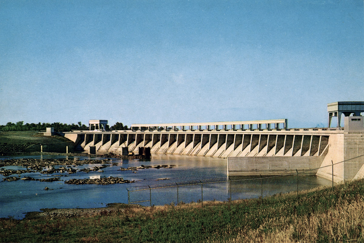
SHCMS006a: Barnhart Island Control Dam
The dam from below looking south. There is no water flowing in this view as all flow down the river is generating power by running through the Moses Saunders Power Dam near Cornwall.
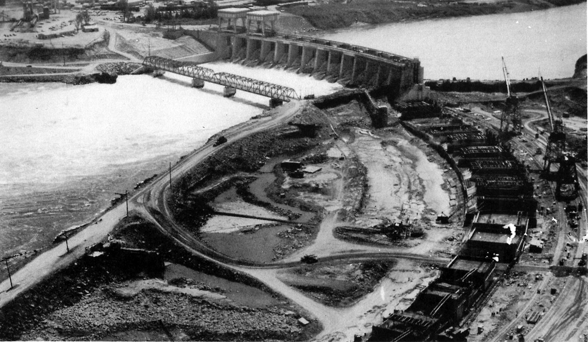
SHCMS007: Barnhart Island Control Dam
Looking down the river over the Barnhart Island Control Dam. The Moses Saunders Power Dam is seen in the distance to the left of the bridge.
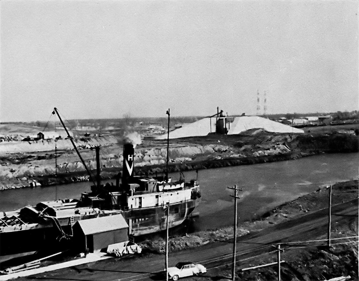
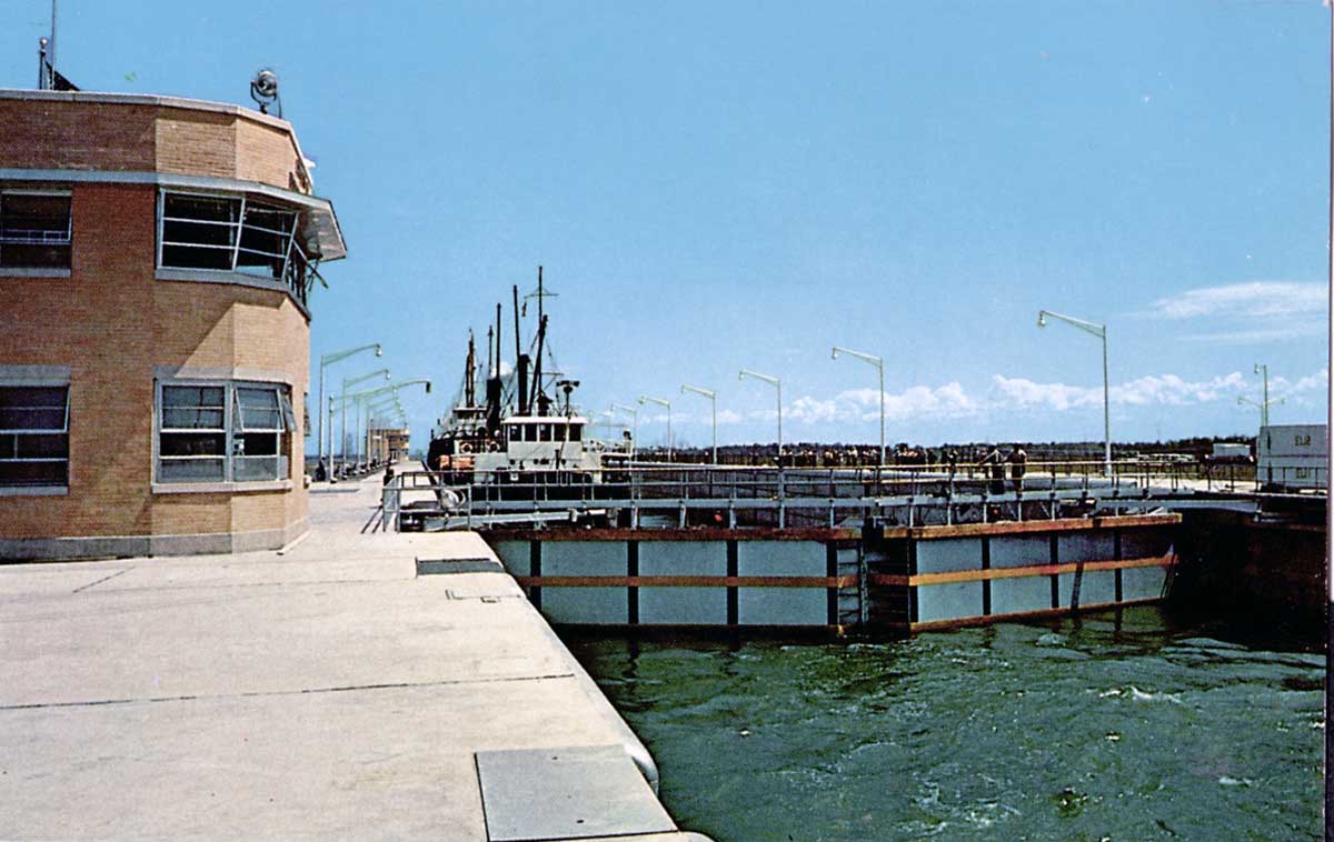
SHCMS008: A ship unloading building materials at the power dam work site.
A Halco canaller is docked in the Cornwall Canal north of the Moses Saunders Power Dam construction site. The ship is delivering cement and other construction materials. In the background can be seen the "gate" which will straddle the Diversion Canal. The dike will be built right up to the top of the gate. When the Diversion Canal is ready for use, ships will pass through the gate.
SHCMS008a: An aerial view of the gate and the Diversion Canal in the Cornwall Canal.
The gate and Diversion Canal were built about one half mile above Lock 19 of the Cornwall Canal. A section of the old canal is now filled in and a tunnel passes under the Diversion Canal. The approach to the tunnel can be seen to the left of the word Canal typed onto the image. The dike to hold back the waters of Lake St. Lawrence is being built on either side of the gate.
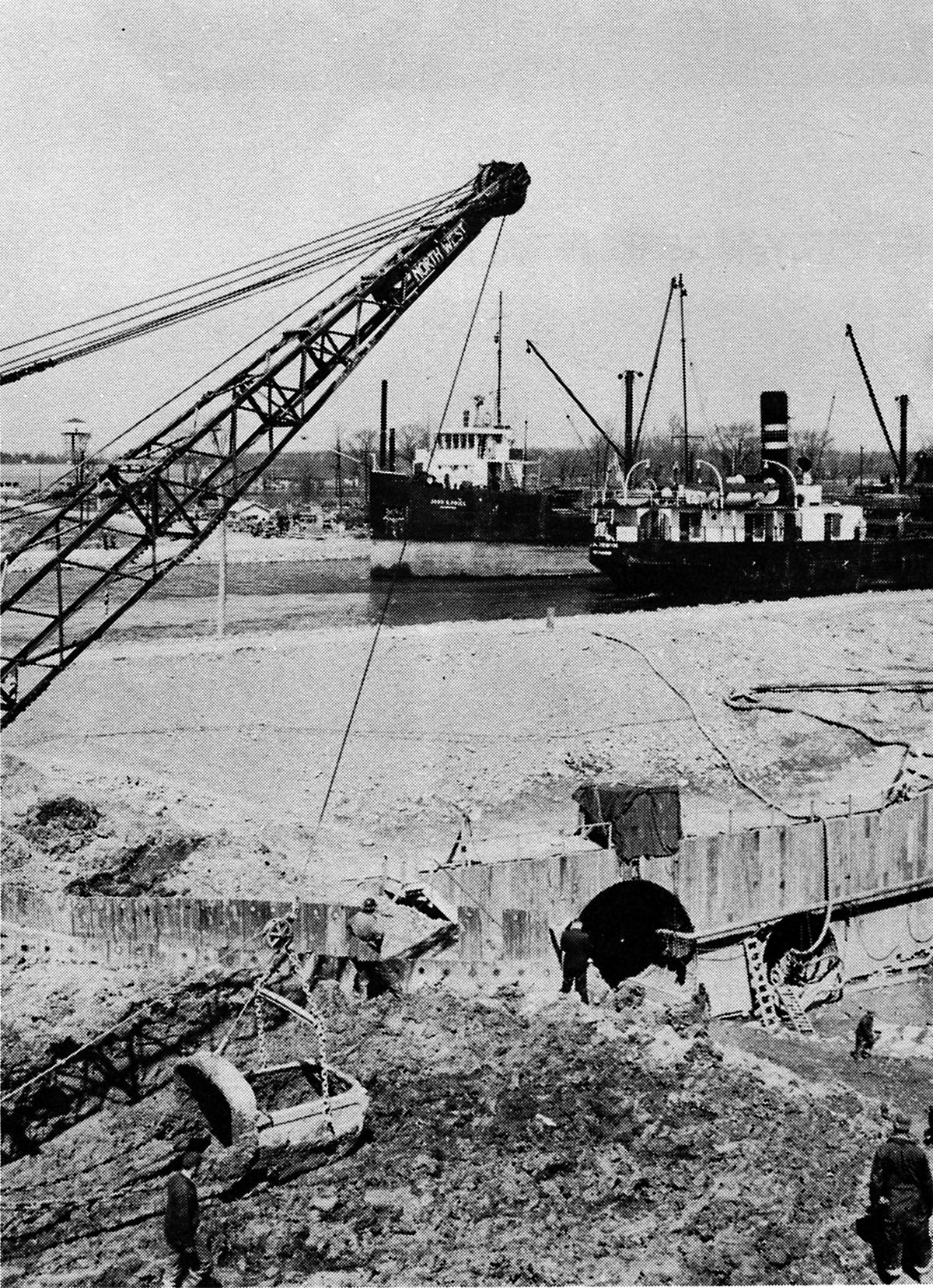
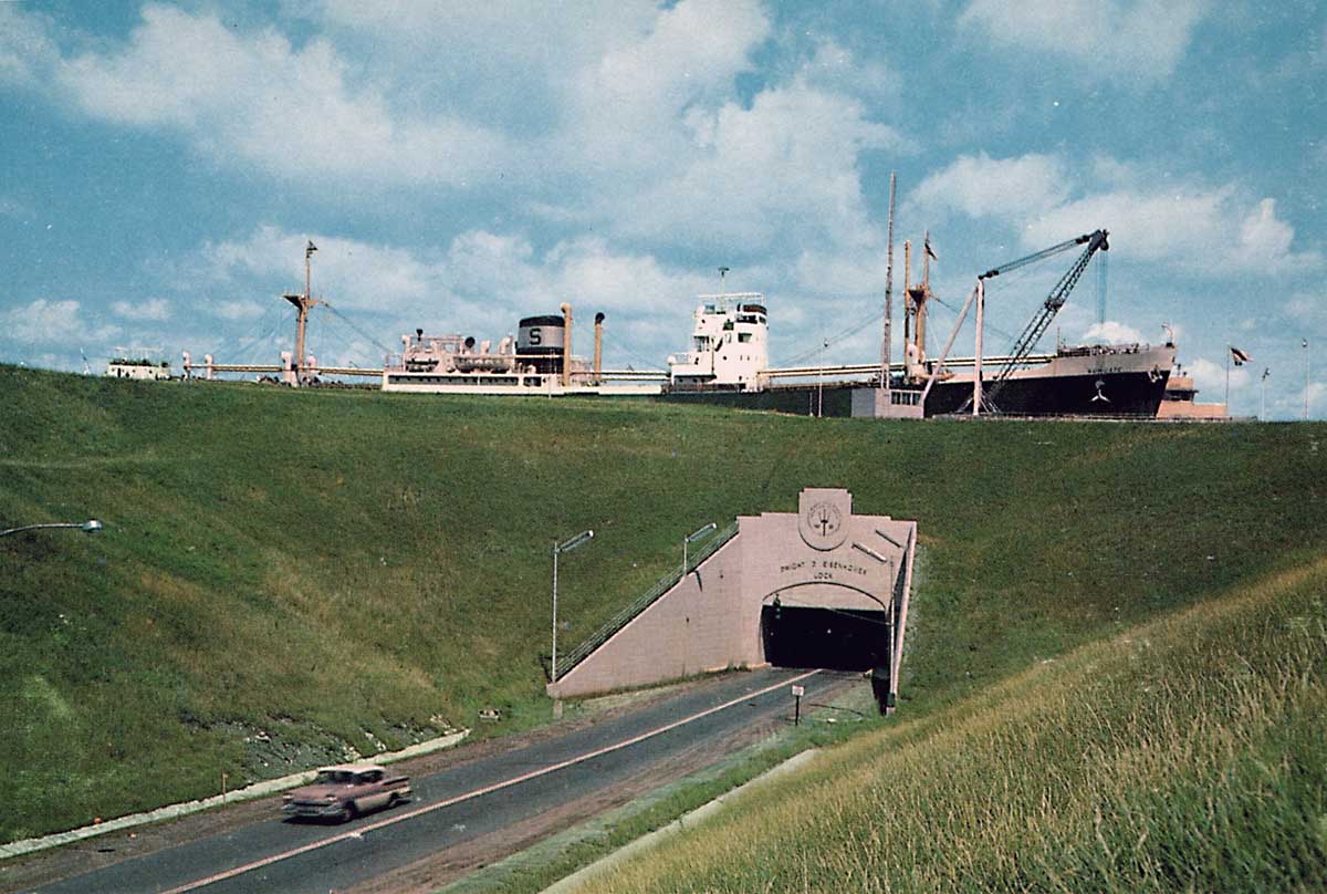
SHCMS008b: Construction tunnel under the Cornwall Canal.
In December of 1954 it was announced that the work on building the tunnel under the Cornwall Canal had begun. The purpose of the twin tunnels was to provide access to the Moses Saunders Power Dam construction site. The large tunnel allowed access for vehicles. The small tunnel had a conveyor belt which brought crushed stone into the cement plant. The two canallers passing above are JOHN H PRICE and J. G. IRWIN.
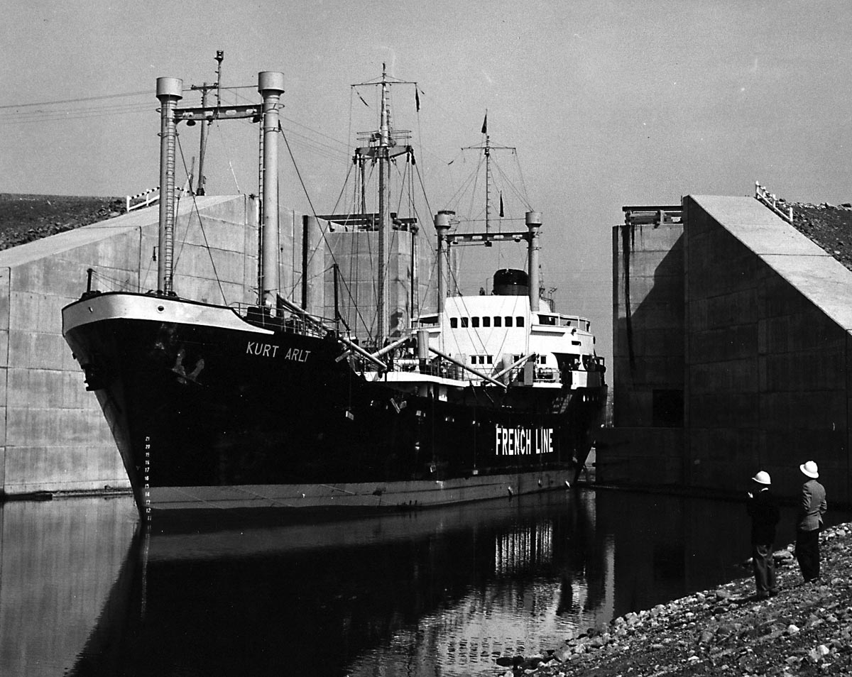
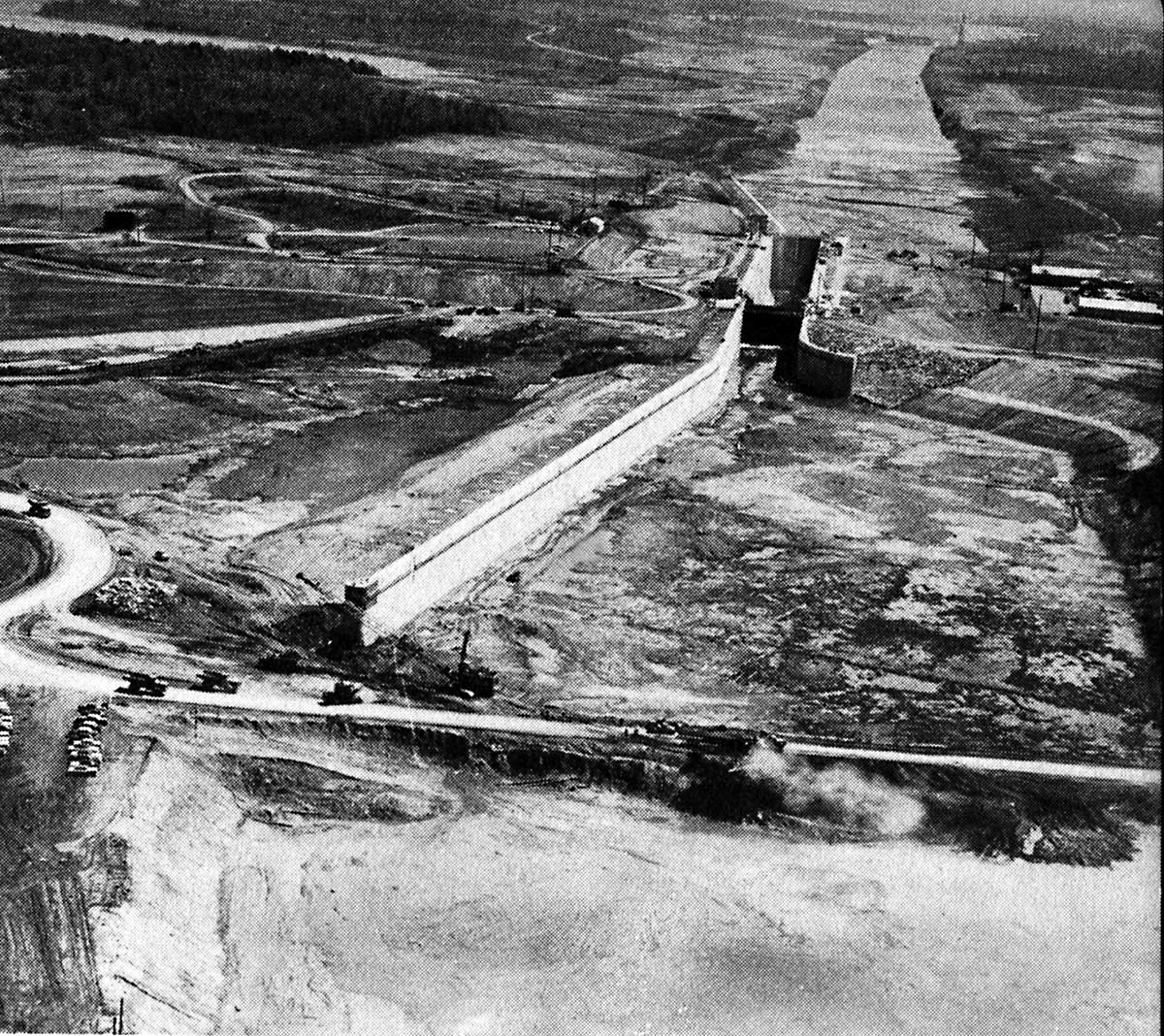
SHCMS009: Ship passing through the gate in the Diversion Canal.
The German flag motor vessel KURT ARLT is on charter to the French Line as she passes up bound through the gate in the dike. The purpose of the gate is to shut off the Cornwall Canal when the Seaway project is completed to the extent that flooding can begin. Note that the dike is now built up to the top of the gate.
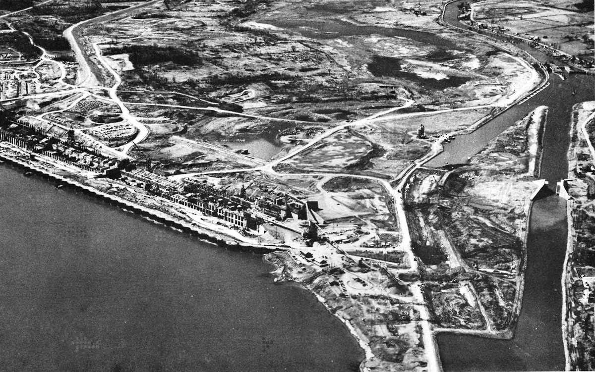
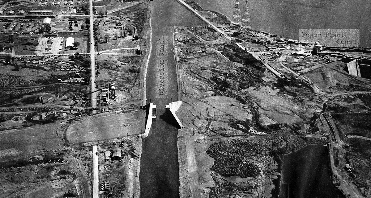
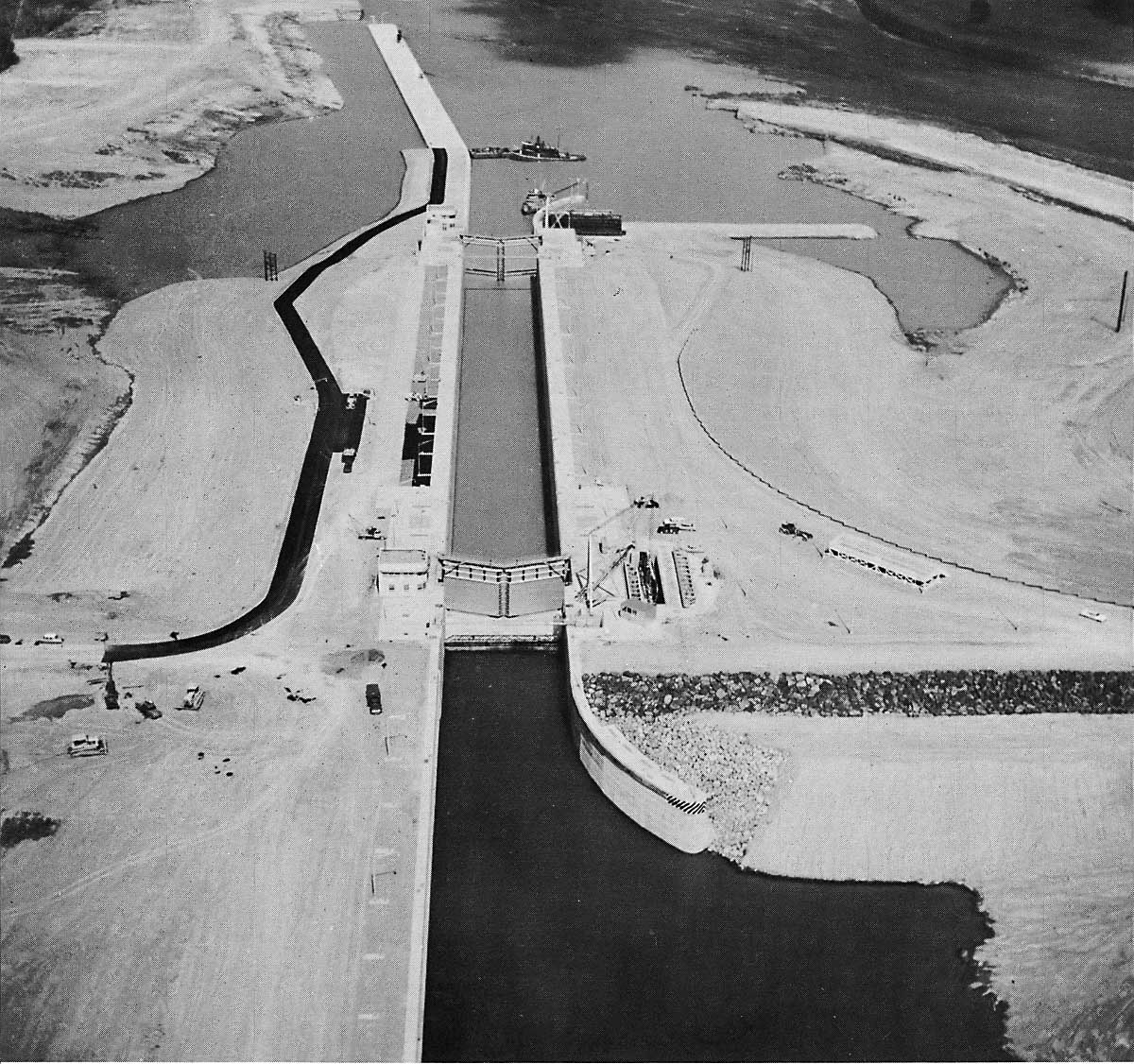
SHCMS009a: Looking west up the Diversion Canal to Lock 20.
This aerial view of the Diversion Canal illustrates how the old Cornwall Canal was cut off and bypassed by the new Diversion Canal. On the right the gate where the canal will be eventually closed off can be seen half way up the Diversion Canal. Beyond it is Lock 20 located at Maple Grove. To the left of the Diversion Canal a portion of the old Cornwall Canal is diked off and now pumped dry. The massive power dam construction site is on the left.
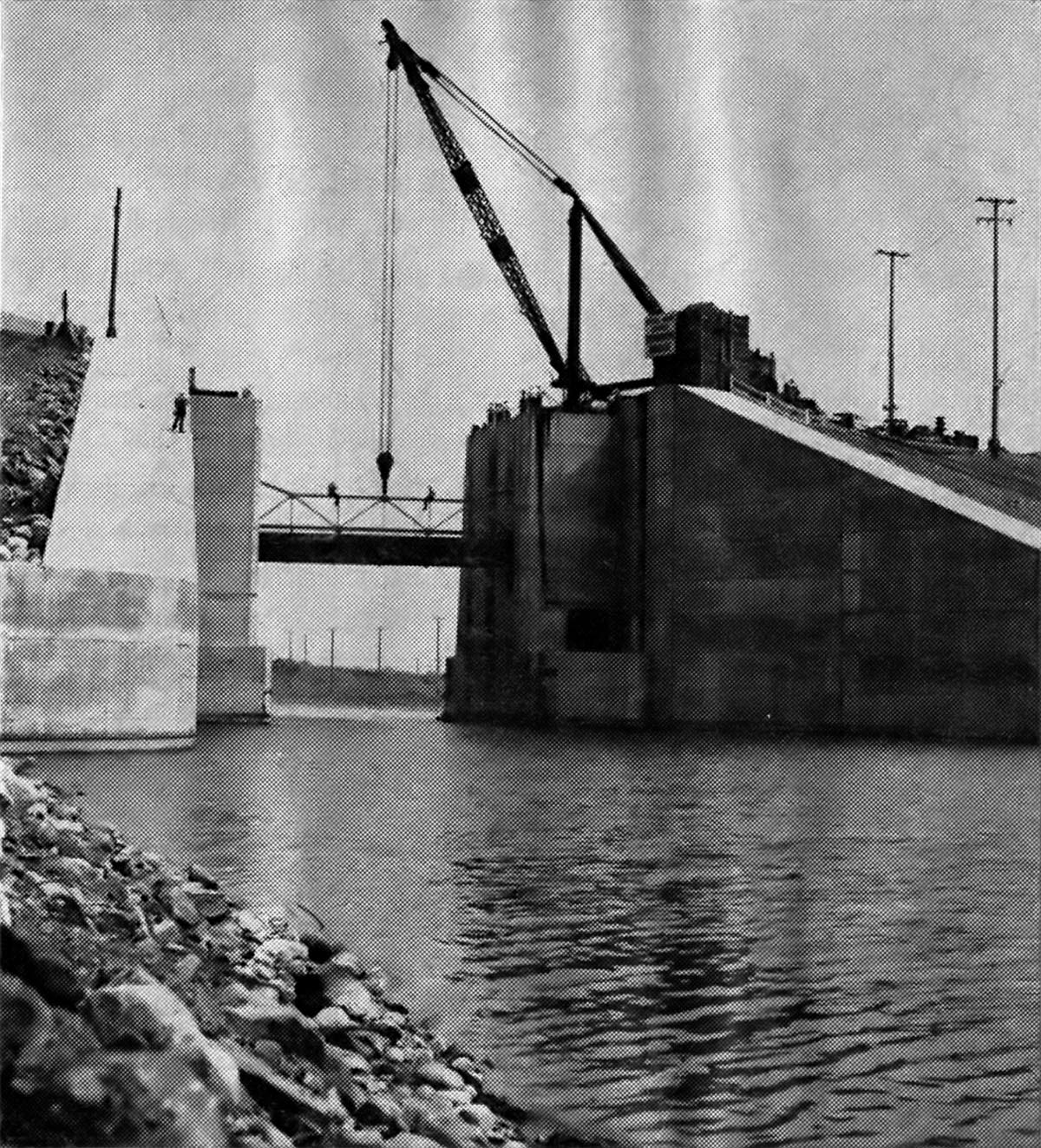
SHCMS010: Closing the gate with stop logs.
In this view of the gate, otherwise known as 'The Canal Closure Structure', the stop logs are being lowered into place, sealing off the Cornwall Canal forever. It is June 29th, 1958, the day before flooding of the St. Lawrence is set to begin. All ship traffic on the river is stopped above and below Cornwall until flooding is complete.
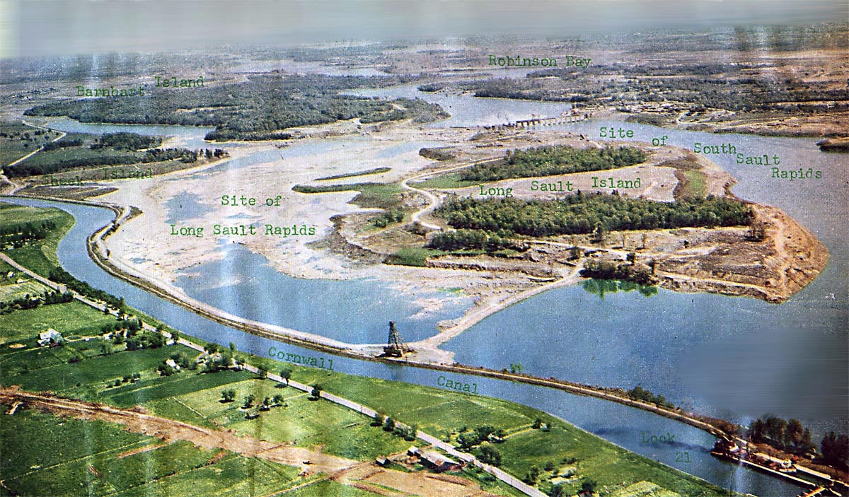
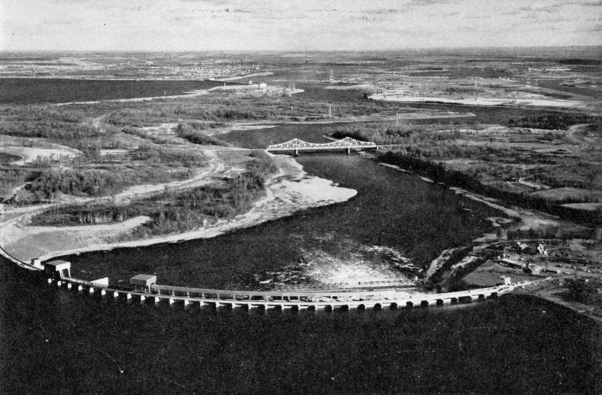
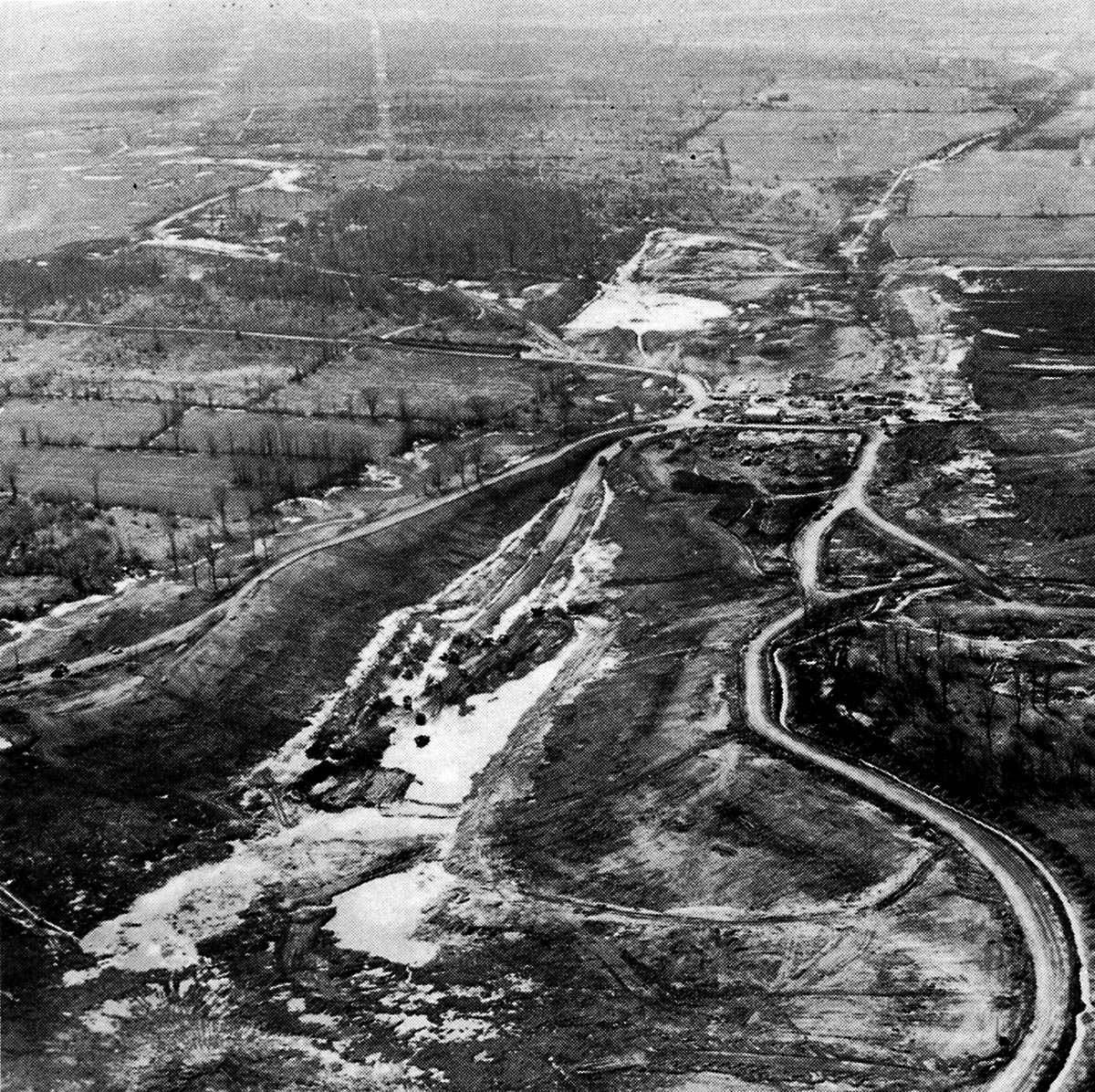
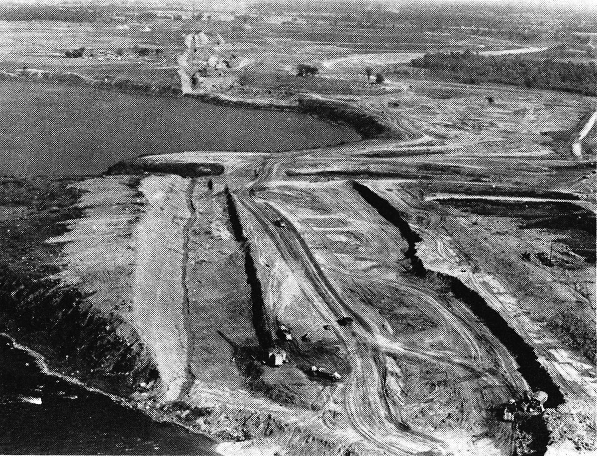
SHCMS011: Aerial view of the Long Sault Rapids cut off by cofferdam
The Cornwall Canal snakes by the now dried up Long Sault Rapids. Lock 21 can be seen on the extreme lower right. The cofferdam was built to divert water away from the Moses Saunders Power Dam construction site located about 6.5 miles down stream and also the north half of the Barnhart Island Control Dam. Note the partially built Barnhart Island Control Dam located below Long Sault Island.
To the right, where it is printed "South Sault Rapids", there is a man made cut through Long Sault Island. The purpose of this cut is to divert water away from the now diked off Long Sault Rapids through to the Barnhart Island Control Dam. A drag line named "The Gentleman" was brought to Long Sault Island from Kentucky to make this cut and others through the island.
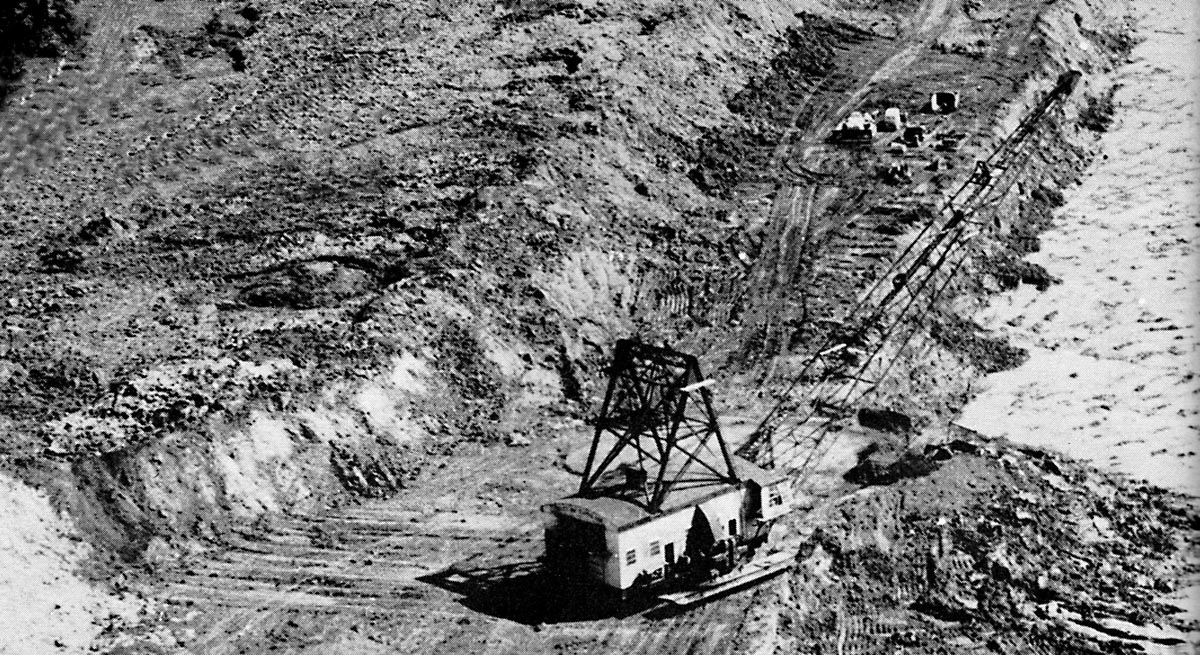
SHCMS011A: A Dragline Called "The Gentleman" Working on Long Sault Island.
"The Gentleman" was brought from the coalfields of Kentucky to Long Sault Island. First it 'walked' 16 miles to the Green River where it was loaded onto a barge. On the barge it traveled under tow down and up rivers to reach the Great Lakes, an inland waterway voyage of well over 2,000 miles that took five weeks. Too big for the canals, it came down the St. Lawrence River rapids until it landed safely at Seeley's Bay on the north west side of Long Sault Island on June 11, 1955.
The Gentleman's job was to cut the island in half by digging a diversion channel through the middle of the island.
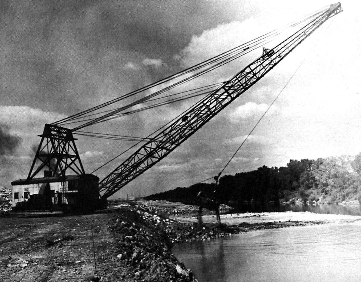
SHCMS011B: The Gentleman at work digging the cut through Long Sault Island.
'"The Gentleman" Takes a 20 Ton Bite'
'Like a proud king buttressing his island domain, a 650 ton walking dragline called 'The Gentleman' is digging three million cubic yards from his three mile strip of the 10 mile Long Sault Canal. His giant steel bucked weighs 14 tons empty. He claws up a 15 cubic yard of rock and earth every 48 seconds, and his 165 foot boom swings and dumps the 20 ton load far back from the canal edge.' - Milwaukee Journal 25 Feb. 1956
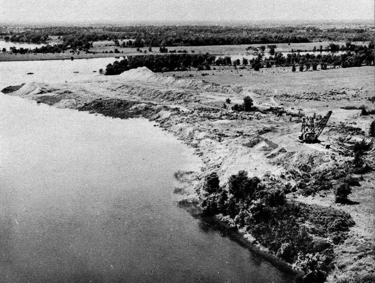
SHCMS011C: An aerial view of the dragline The Gentleman on Long Sault Island 1955.
There were three cuts through the Island made by The Gentleman and another smaller drag line brought there from Kentucky.
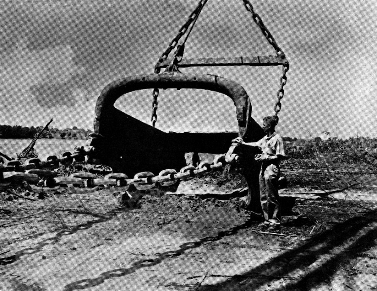
SHCMS011D: The Bucket used by The Gentleman.
A good comparison is a man standing next to the bucket used by "The Gentleman" to cut channels through Long Sault Island. When full it contains 15 cubic yards of earth and rock estimated to weigh twenty tons.
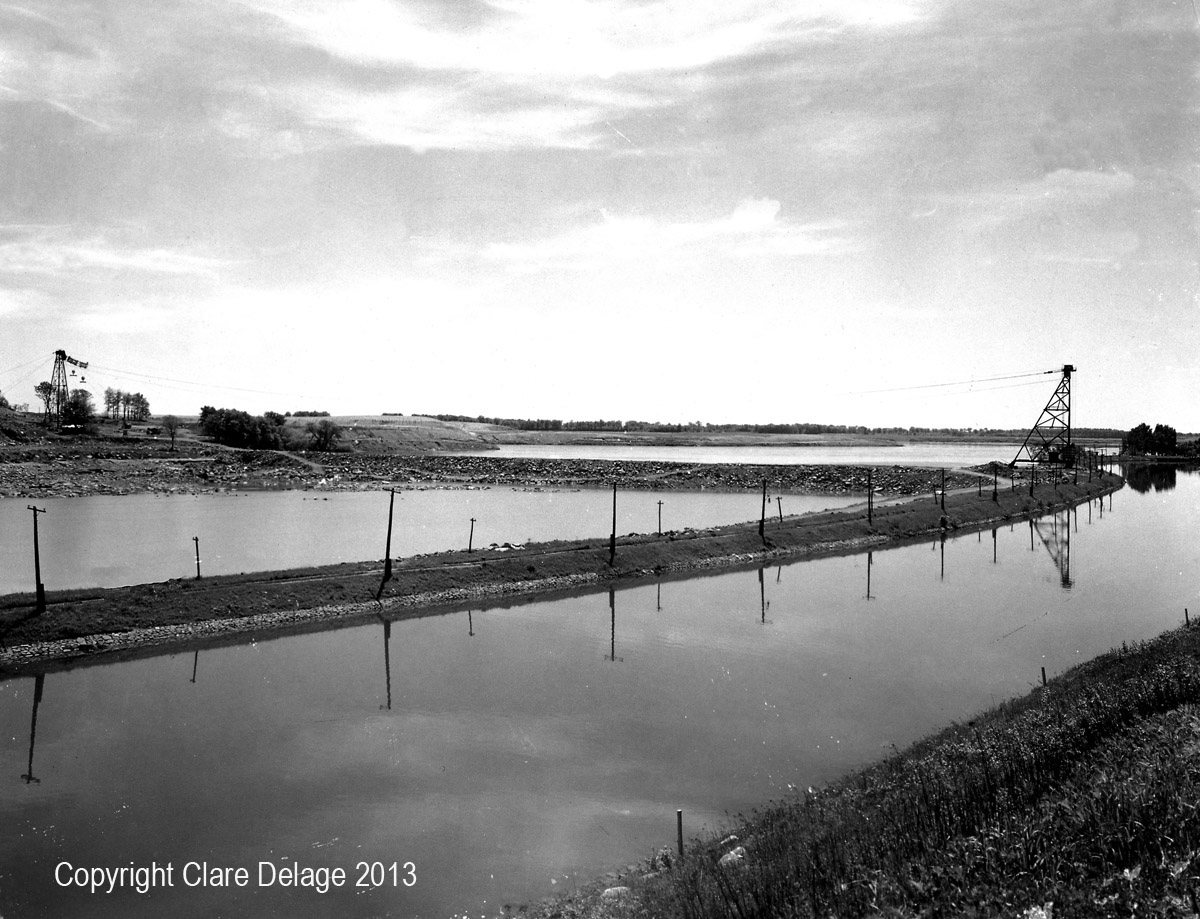
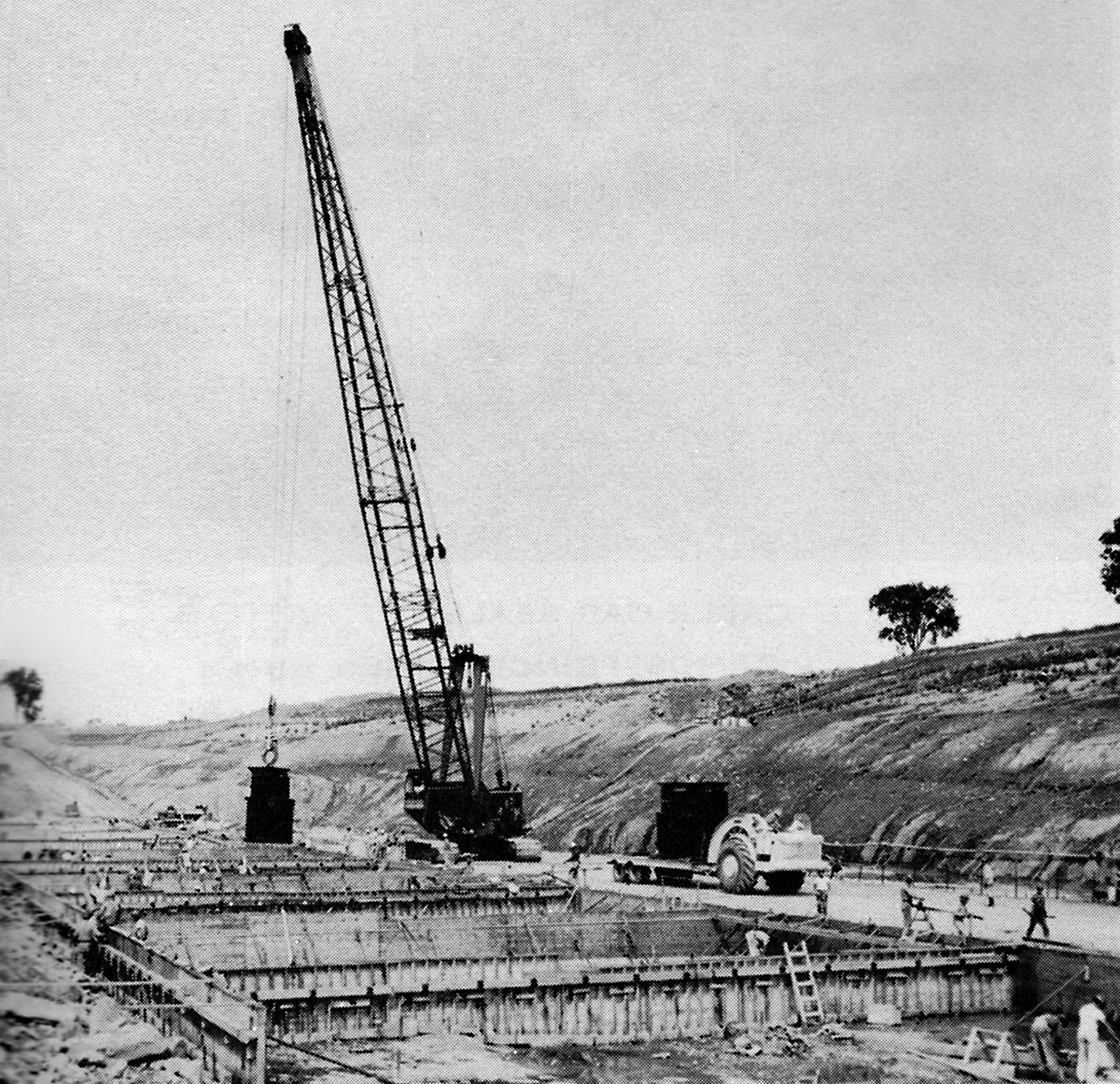
SHCMS012: Cofferdam E from Long Sault Island to the Cornwall Canal.
The building of Cofferdam E began with the construction of two towers used to drop loads of rock, up to 25 tons, into the Long Sault Rapids. Beginning in the fall of 1956, the work carried on throughout the winter until April 1957. The tower on the left is located on Long Sault Island. The tower on the right is on the bank of the Cornwall Canal just below Lock 21 at Dikinson's Landing.
Photograph by Reverend George H. Smith.
.jpg)
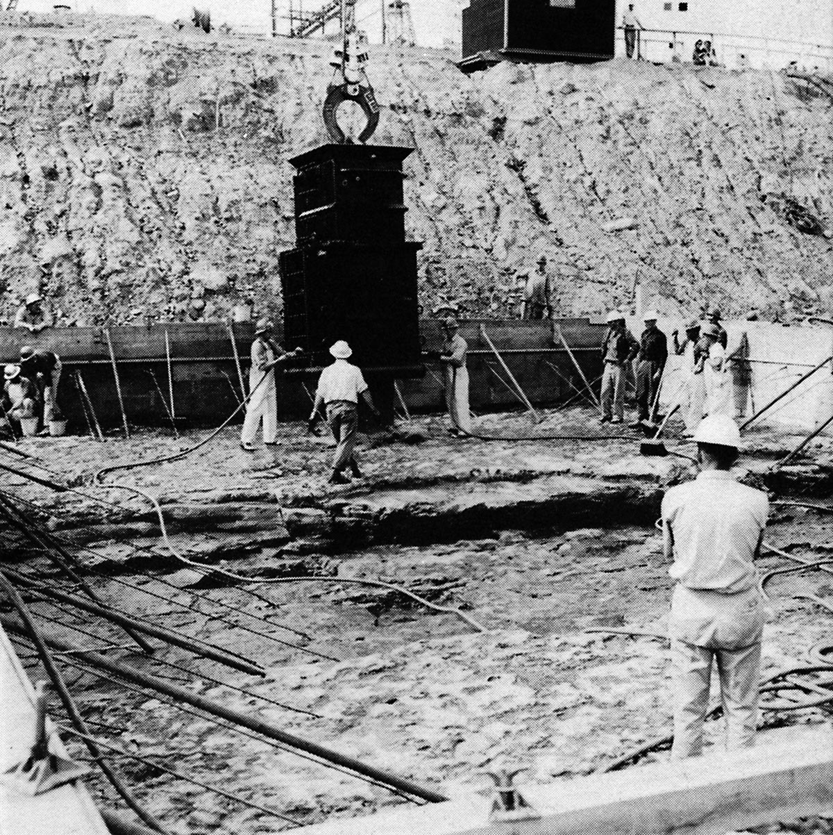
SHCMS012a: The bucket used to build Cofferdam E.
The bucket crossing the river on cables strung between the towers located on the canal bank and Long Sault Island. Note the men going along for the ride upon the trolley.
The dam was built out from the banks of the river. Once the gap narrowed to less than 100 yards, the force of the water washed most of the rocks dropped into the current down stream. The closure of the gap became nearly an impossibility as single chunks of stone weighing over 20 tons were dropped into the gap only to be washed away.
Finally a device built out of welded girders with six steel legs, called a hexapedian, was dropped into the gap. The first one was washed away but the second was loaded with large stones shortly after it was dropped into place. Finally the dam was complete after seven months of work.
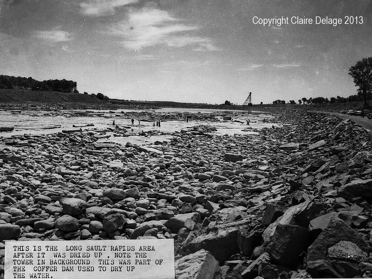
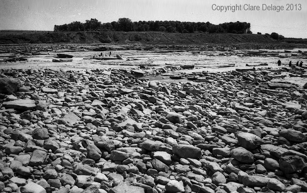
SHCMS013: The Long Sault Rapids dried up
People drove from miles around to see the spectacle of the bottom of what was one of the largest rapids in North America.
Arthur Raymond, a boy from Sheek Island, found eleven cannon balls dating from the early nineteenth century.
Photograph by Reverend George H. Smith.
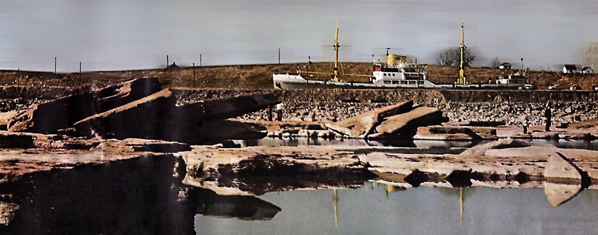
SHCMS014: The PRINS WILLEM IV passing the dried up Long Sault Rapids.
The Dutch flag ship PRINS WILLEM IV sails up the Cornwall Canal past the Long Sault Rapids which have been dewatered by the building of the coffer dam just below Dikinson's Landing. The photo was probably taken from Long Sault Island looking north.
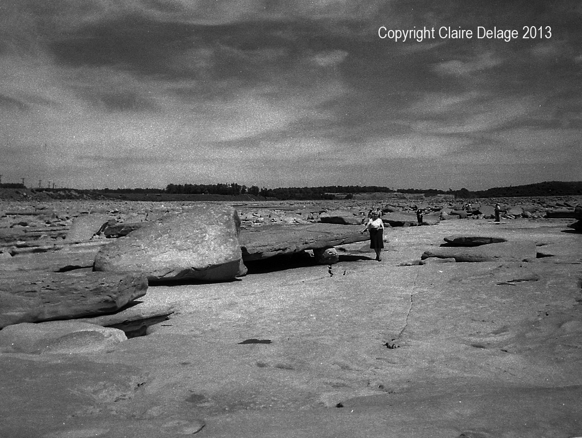
SHCMS015: The rocky bottom of the former Long Sault rapids.
A view looking east down the river bottom which once was the Long Sault Rapids. This amazing spectacle drew hundreds of people from the area to walk on the bottom of the river. To the left is the bank of the Cornwall Canal.
Photograph by Reverend George H. Smith.
SHCMS016: Long Sault Rapids looking south west towards Long Sault Island.
The dry rocky bottom of what was once the Long Sault Rapids. In the background can be seen Long Sault Island with a forest of trees still standing upon it. The cofferdam which blocked the flow of water through this area is on the far right.
Photograph by Reverend George H. Smith.
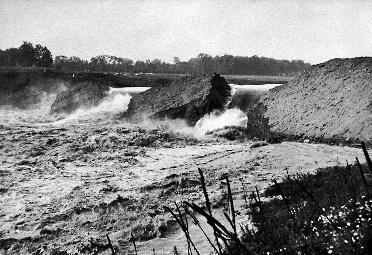
SHCMS016a: Breeching the Dike.
Charges of dynamite break open one of the dikes holding back the St. Lawrence. Once the blasting has breeched the dike, the water will cut through and wash away the remaining dam. This was the beginning of the flooding late in June 1958.
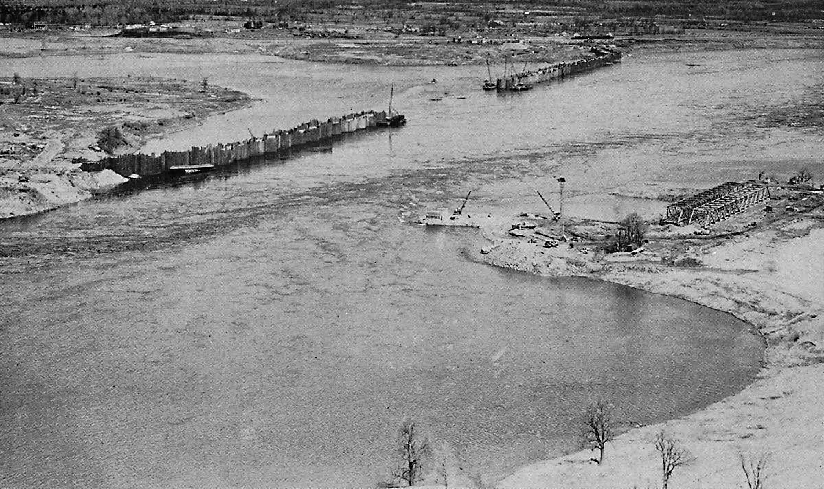
SHCMS016b: Moses Saunders Dam Early Stage.
Looking north from the N.Y. State side of the river a short distance above Cornwall, Ontario. The cofferdam, behind which will rise the Moses - Saunders Power Dam, is just beginning to take shape. The two spans of the bailey bridge can be seen to the right. They will be placed on temporary piers to reach across to Barnhart Island to the right. This will give American workers access to their side of the construction site.
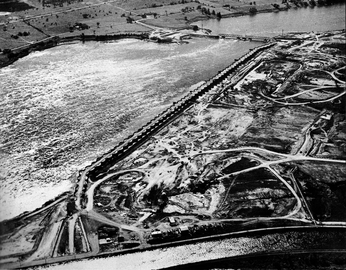
SHCMS017: Steel cofferdam stretches from the Ontario mainland to Barnhart Island.
This steel cofferdam is over 3500 feet long. It is located just above the city of Cornwall and shelters the location of where the Moses Saunders Power Dam will be built from the rapids running close by. The Cornwall Canal can be seen at the bottom of the image. A temporary bailey bridge runs across the rapids from the U.S. end of the cofferdam on Barnhart Island to the U.S. mainland of New York State.
.jpg)
SHCMS018: The footings for the new power dam are in place.
After 2,200,000 cubic yards of earth and rock were excavated, the forms for the new footings for the power dam were built. The U.S. side of the dam, towards the right, seems to be more complete than the Canadian side on the left.
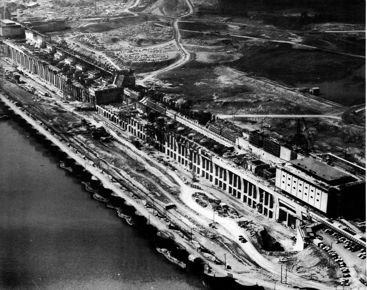
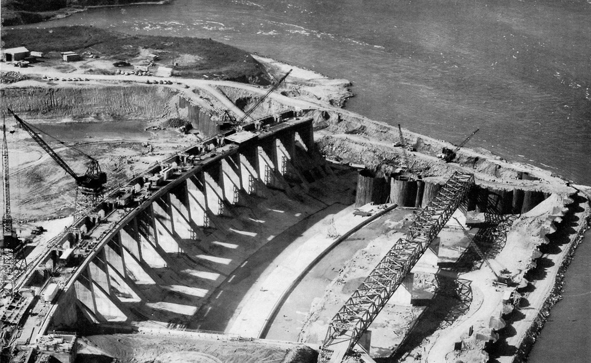
SHCMS019: Looking from the Canadian side of the power dam construction site.
Each half of the dam was 1,608 feet long. The dam was built to a height of 167 feet. Each half required 887,000 cubic yards of concrete and 37,500,000 pound of reinforcing steel. In each half there will be 16 turbine generators, each rated at 71,000 horsepower.
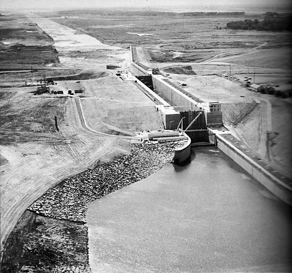
SHCMS019a: Moses Saunders Dam from the South or U.S. Side.
The Moses - Saunders Power Dam under construction as seen from the U.S. side of the river. At the very top of the image the Cornwall Canal can be seen. Also the new dike from the power dam to the closure structure straddling the old canal is nearly complete.
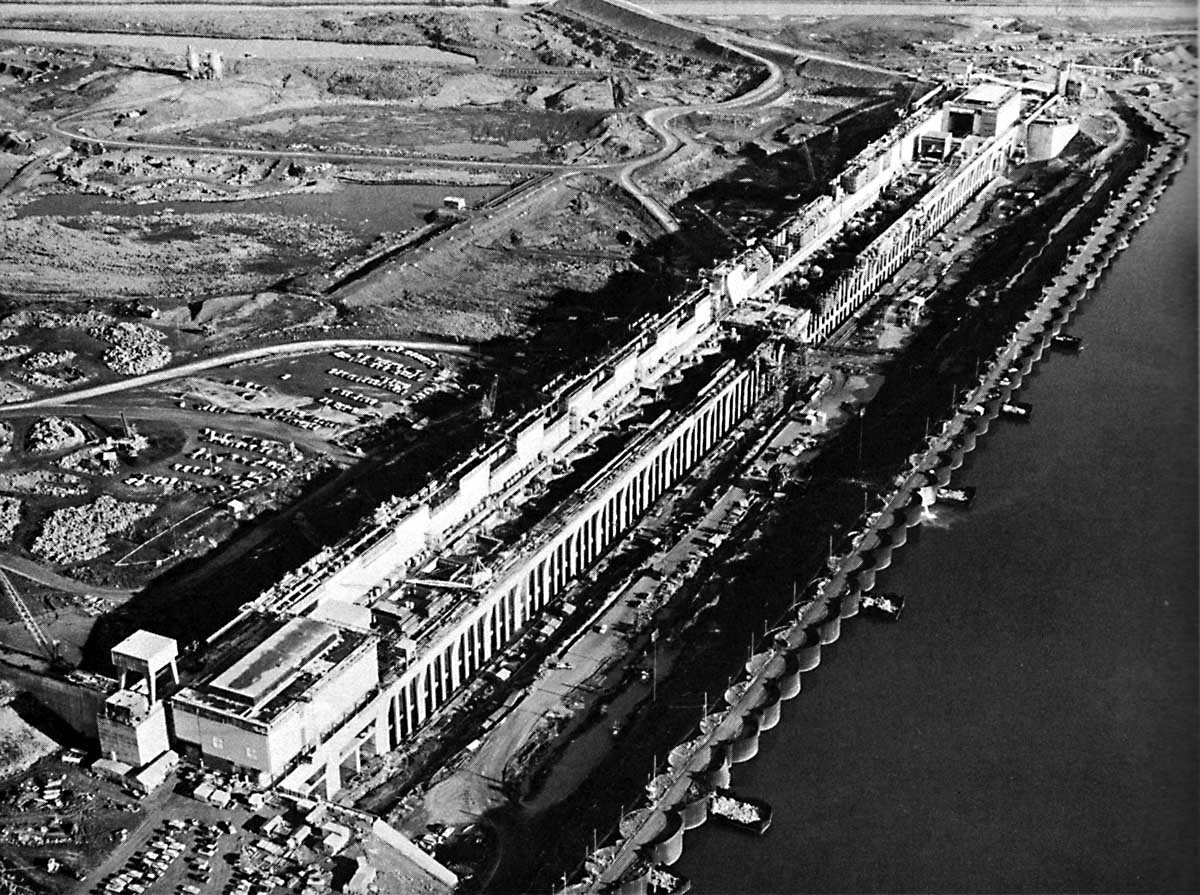
SHCMS020: The Moses Saunders Power Dam nearing completion.
The cofferdam below the power dam construction site has been breeched and the removal process is under way. The dike which will hold back the water is now nearing completion as well. The head pond, or Lake St. Lawrence, will be 81 feet deep at the dam. The closure structure which will seal off the Cornwall Canal on flood day is seen at the bottom of the photo.
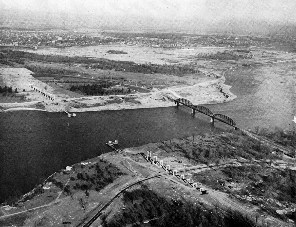
SHCMS021: Bridge from New York State to Cornwall Island.
To the right is the New York Central Railroad Bridge which was completed on October 1st, 1900. This was the site of a terrible disaster when this bridge collapsed on September 6, 1898, while it was under construction. Seventeen workers were killed. The new high level bridge under which ships will sail is under construction on the mainland and Cornwall Island.
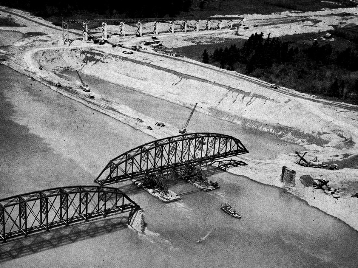
SHCMS021A: Floating away a section of the NYC bridge in 1958.
Suspended on barges, the first section of the south span of the old road and rail bridge is floated away for scrapping nearby. In the background there is what appears to be a large trench, but it is actually a section of Cornwall Island being carved away to widen the new shipping channel.
The new high level bridge is under construction on Cornwall Island. Once the old bridge was taken out of commission, two automobile ferries were brought from the East Coast of the United States to carry cars from New York to Cornwall.
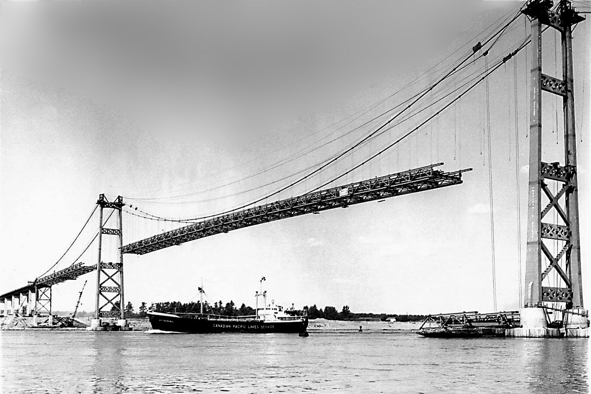
SHCMS022: International High Level Bridge Under Construction.
A German flag salt water ship, the OTTO NUBEL, is seen passing beneath the new high level international bridge, still under construction. The steel bridge sub assembly sitting on the barge at the base of the tower on the right will be hoisted up to the same level as the partially assembled bridge deck.
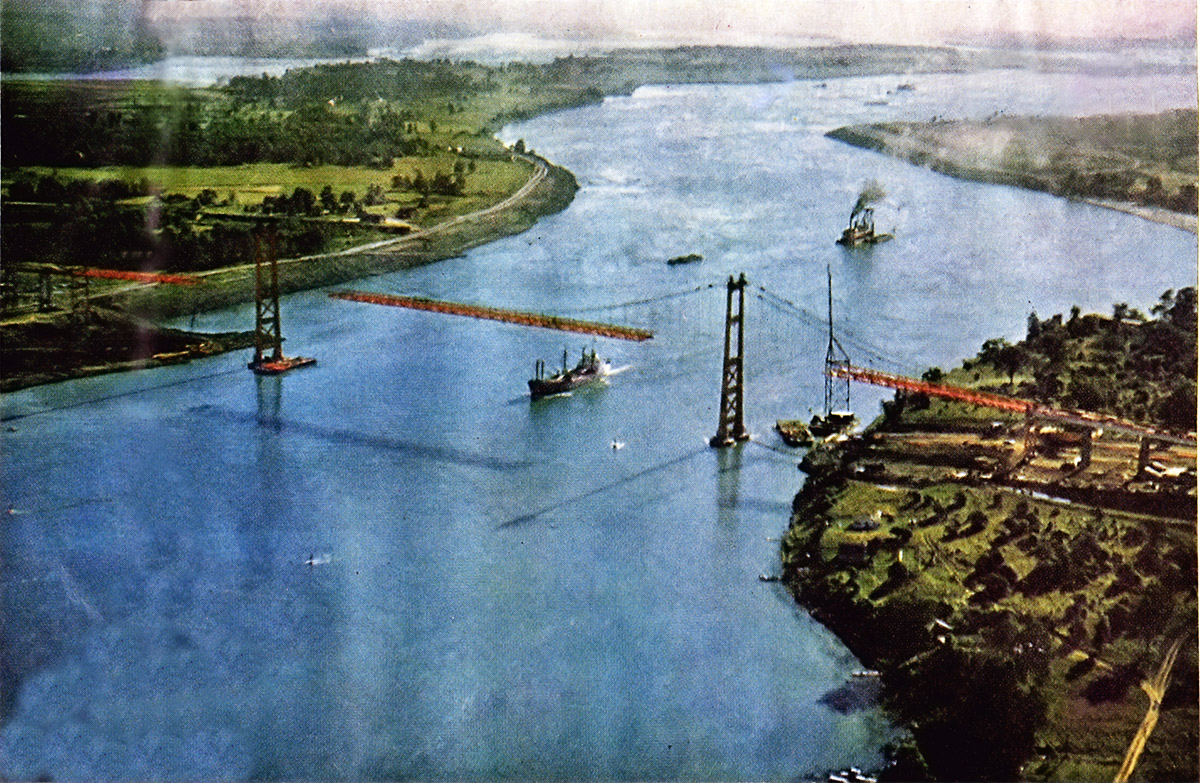
SHCMS023: Aerial view of Cornwall Island bridge under construction.
Cornwall Island is to the left and New York State is to the right. A ship is seen passing under the bridge while in the background a dredge is still working on digging the new shipping channel down stream of the bridge.
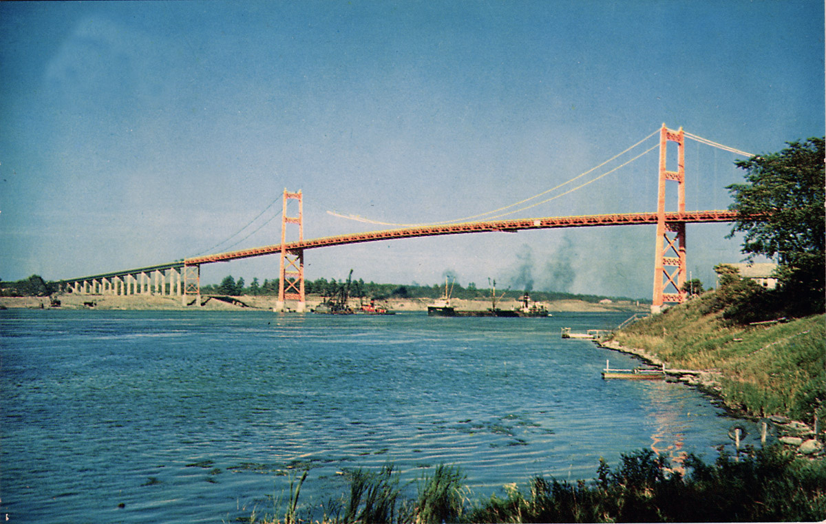
SHCMS024: Cornwall Island bridge to New York State.
A Misener Shipping canaller steams under the new high level international bridge while workers put the finishing touches to it. The bridge was formally opened on July 3, 1962.
U.S. side of the Cornwall - Massena Seaway Construction
The next series of illustrations covers the U.S. side of the Cornwall - Massena Seaway construction area, including a ten mile long canal and two lift locks. This canal bypassed the St. Lawrence Power Project. The new canal is 442 feet wide at the bottom and a minimum of 550 wide at the surface. Excavation for the canal entailed removing more than 16,625,000 cubic yards of glacial till and marine clay. The digging of this canal began early in 1955. It was completed by December of 1957.
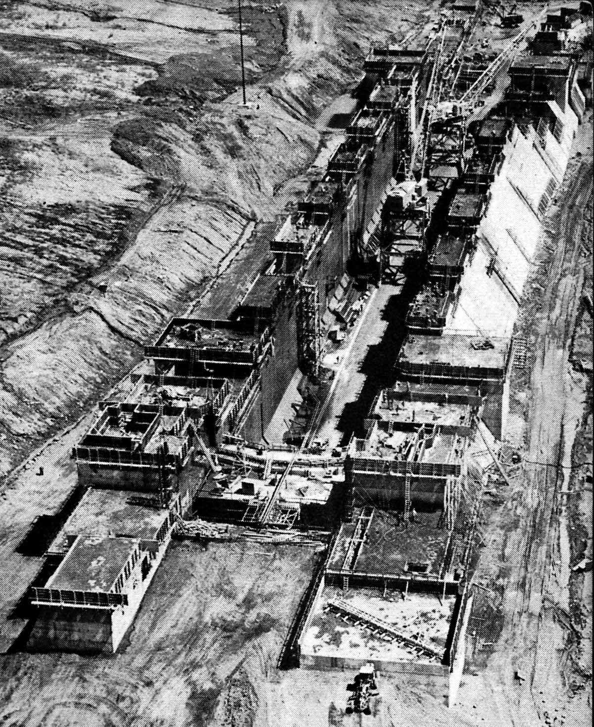
SHCMS025: Excavation of the Snell Lock.
The beginning of the excavation for the Snell Lift Lock early in 1955. Once bedrock was reached, a fracture in the rock was discovered which proved to be a geological fault. The site for the lock had to be relocated a few hundred yards further east. Total volume of material excavated was 3.5 million cubic yards.
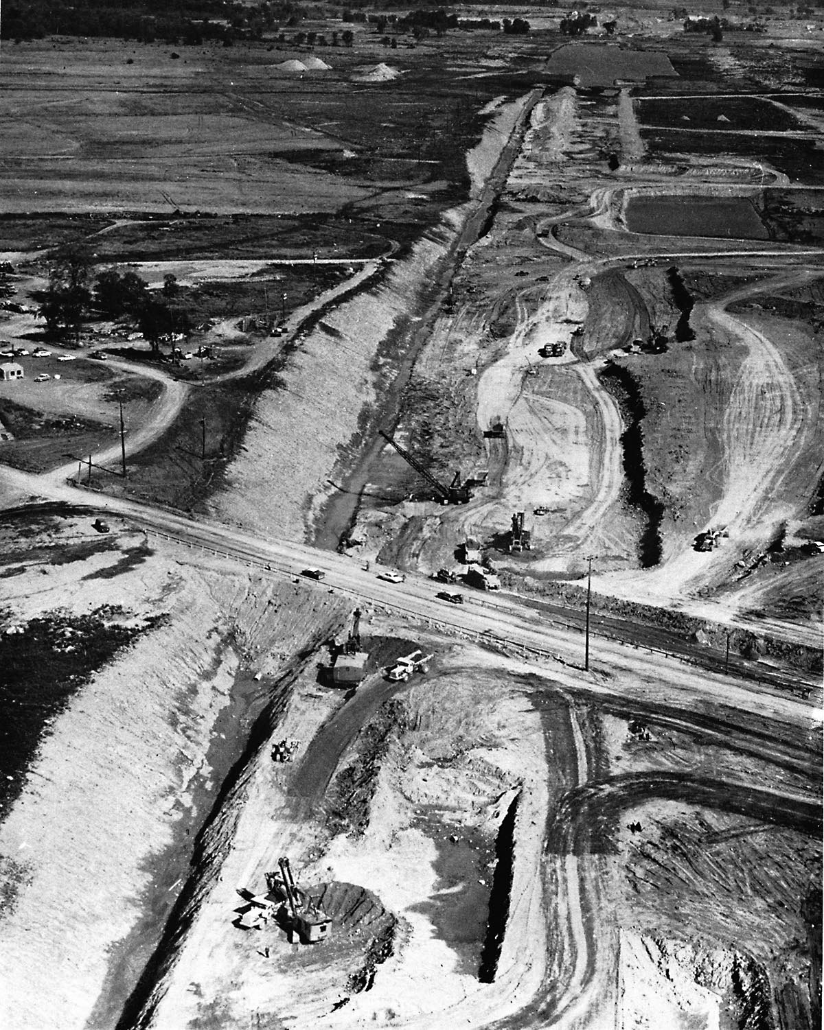
SHCMS025A: Excavation of the Wiley-Dondero Ship Canal.
Farmlands succumb to the earth movers as the new ship canal is carved out between the two lift locks in the summer of 1955. This view is looking east towards the site where the Snell Lock will soon stand. Most of the material excavated will be placed in the dikes along the shore of the river.
SHCMS026: Forms for Concrete Pouring at Snell Lock.
This view shows the first forms in place for building the Snell Lock. Total amount of concrete for this lock was 376,000 cubic yards.
SHCMS027: First Pour of Concrete at Snell Lock.
On July 16, 1956, the first concrete was poured into a form at the site of the Snell Lock.
SHCMS027a: Snell Lock Summer 1957.
This view of the partially constructed Snell Lock in the summer of 1957 must have been taken on a Sunday as very few workers can be seen. In just one year since the first pour of concrete, much progress has been made. The upper sill of the lock is near the bottom of the photograph as we are looking east or down the canal.
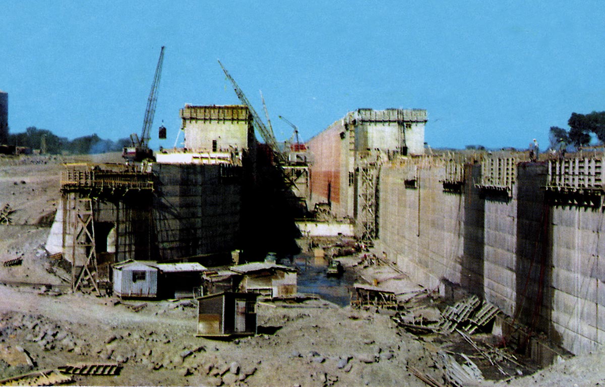
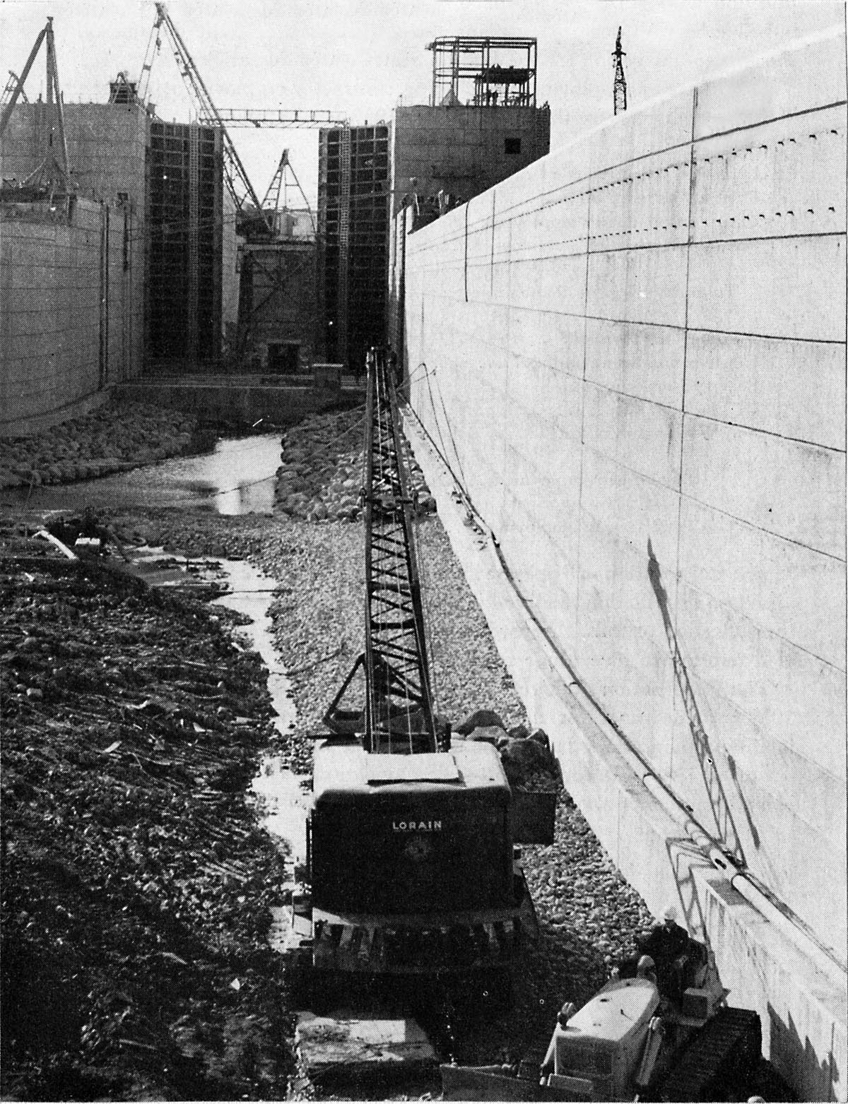
SHCMS028: The Snell Lock Construction Site.
Looking west at the lock as it rises from the bedrock. The forms rise up as the concrete is poured in. The lock walls are 80 feet apart.
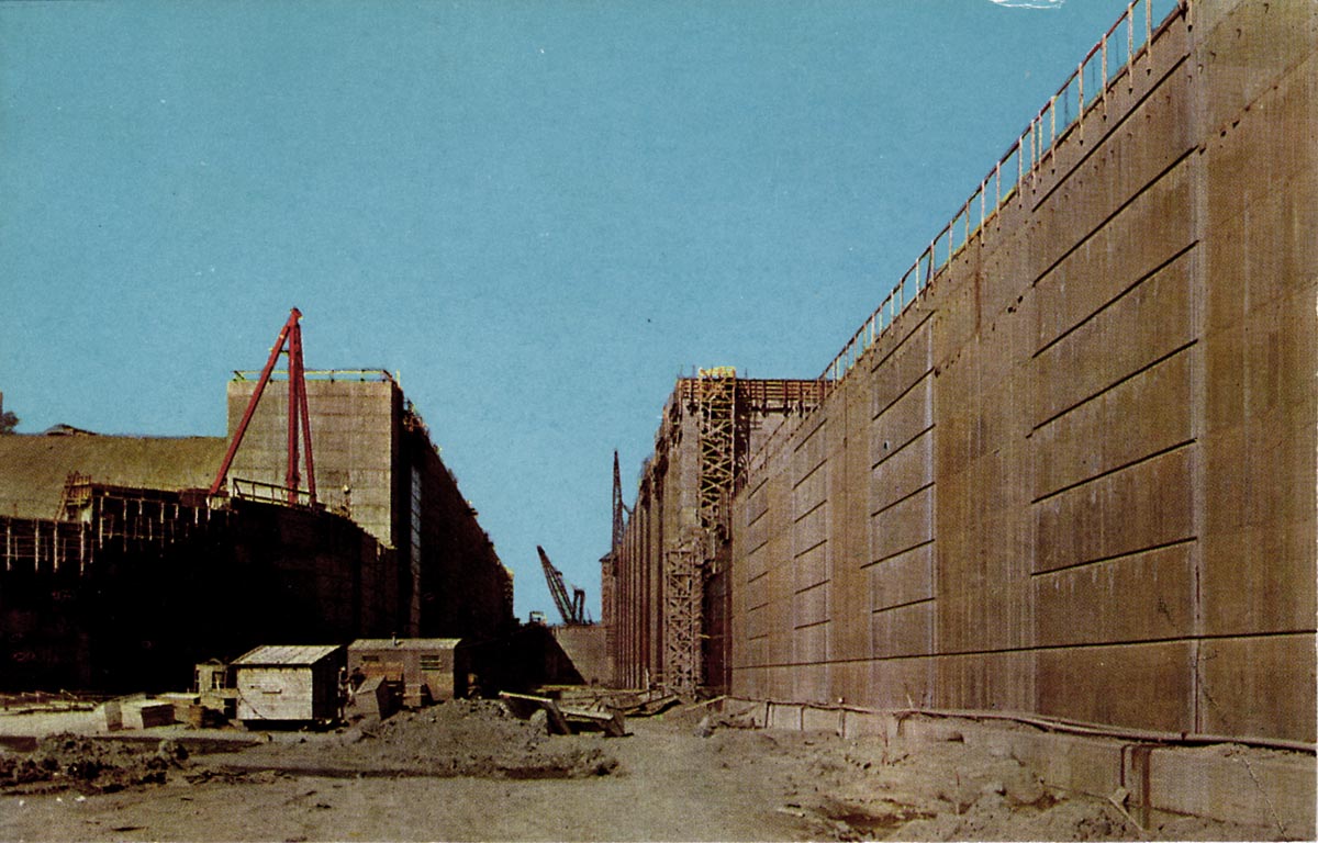
SHCMS029: The Snell Lock Concrete in Place.
The new lock walls rise 113 feet above the bedrock. In the distance, at the far end of the lock, the upper sill can be seen.
SHCMS030: Crane inside the Snell Lock.
The traveling crane stands inside the Snell Lock near the lower end of the lock. To the left of the crane is a recess in the wall where one of the miter type gates will be installed.
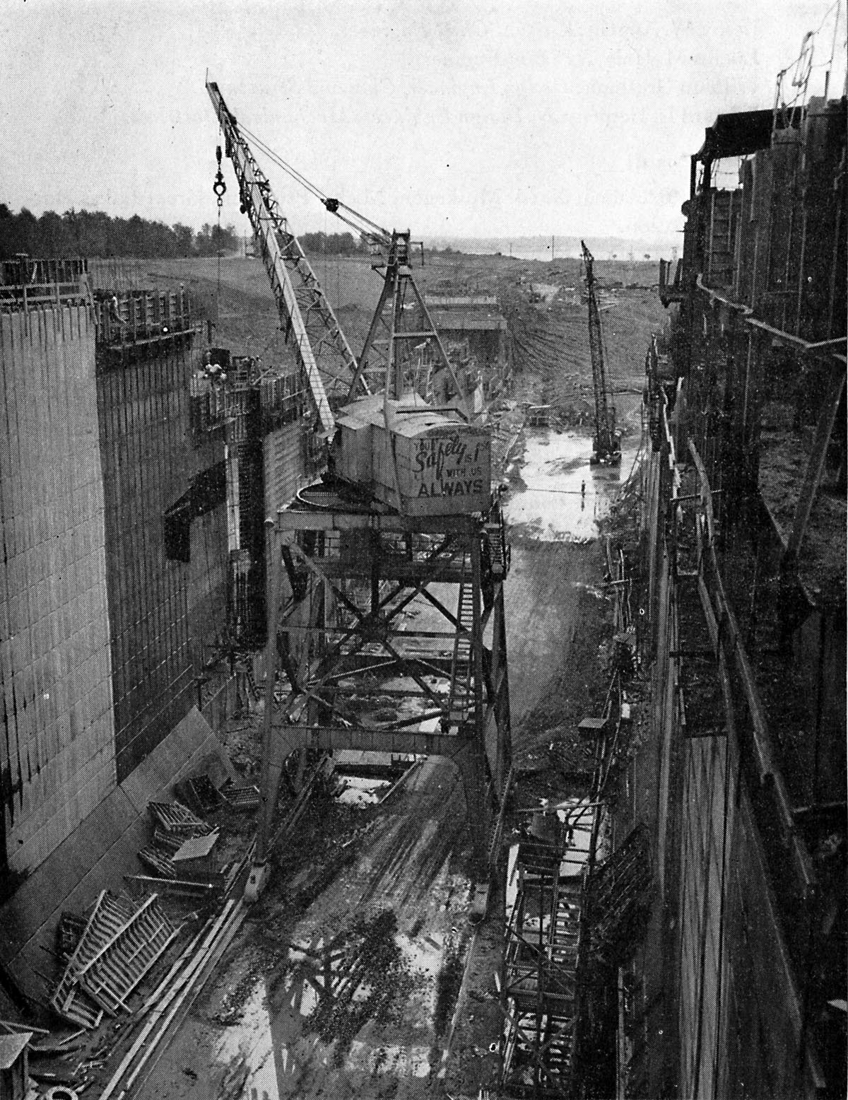
SHCMS031: Snell Lock Construction.
Looking up into the Snell Lock from the east end. The miter gates at the lower end of the lock are completely assembled and left in a partially closed position with a temporary footbridge across the top for the passage of workers. The traveling crane remains inside the lock but will soon be removed.
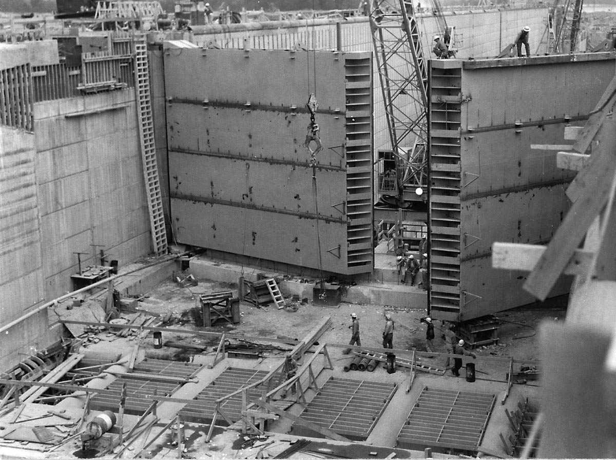
SHCMS032: Snell Lock Upper Gates in 1957.
The upper gates at Snell Lock appear to be completely assembled in this view looking inside the upper end of the lock. When flooded there will be about 30 feet of water in this area.
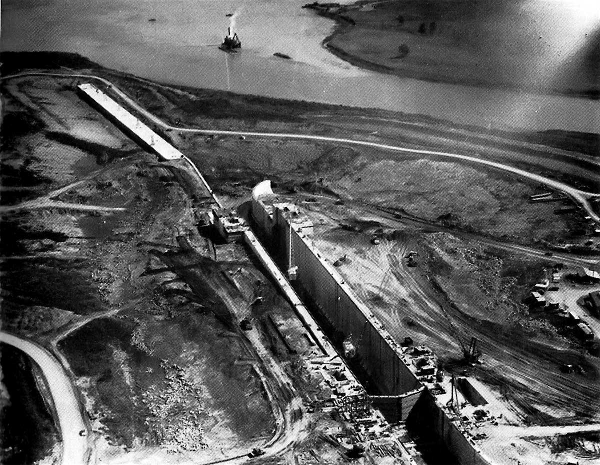
SHCMS033: Snell Lock Nearly Completed.
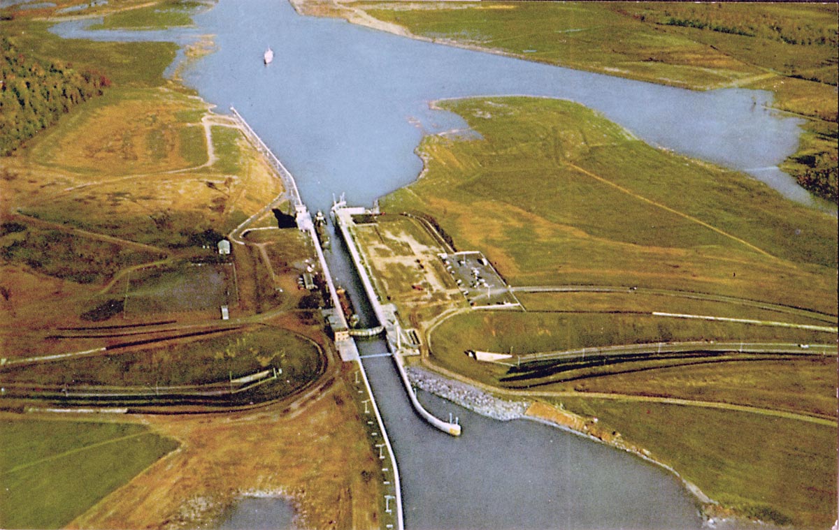
An aerial view taken in 1957. All concrete is in place and landscaping around the lock is in progress. The upper gates are closed.
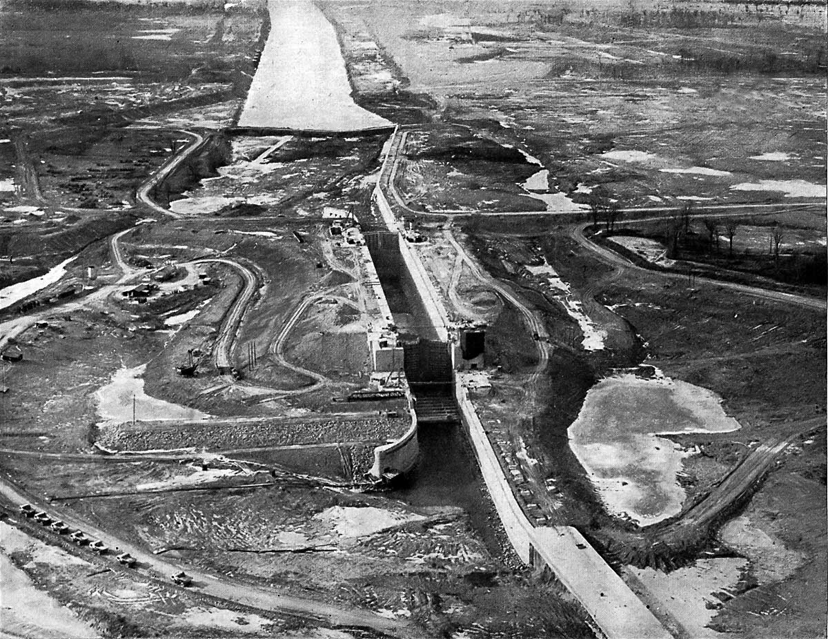
SHCMS034: Snell Lock About Ready for Water
This aerial view must be spring 1958. Both sets of miter gates are closed and only the coffer dams are keeping the water from flooding the lock from above and below.
SHCMS035: Snell Lock Flooded in 1958.
The lower coffer dams have been removed. The tug ROBINSON BAY is moving a barge below the lock but the water above the lock is still too low for vessels to transit. Above the lock it will be at least 30 feet higher before long, when the Wiley-Dondero Ship Canal is filled to the normal level.
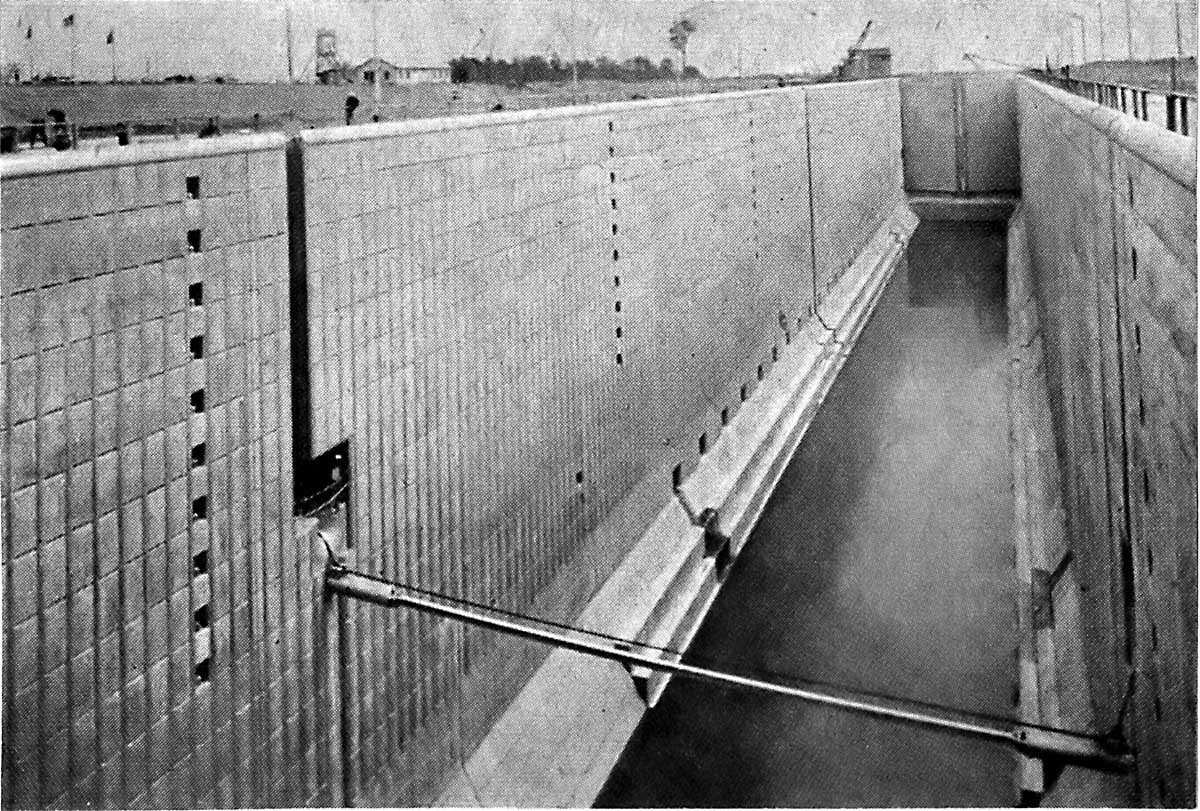
SHCMS036: A Look Inside the Finished Snell Lock Chamber.
The water level is still far below normal in this view. The lock has some water in it but normally when an upbound ship is entering the lock, it is about 30 feet deep. When a down bound ship is entering the lock through the upper gates, which we see closed in this image, the water level is about 73 feet deep.
The bar and cable across the lock is a ship arrestor. This prevents a ship from crashing through the lower gates when down bound and entering the lock.
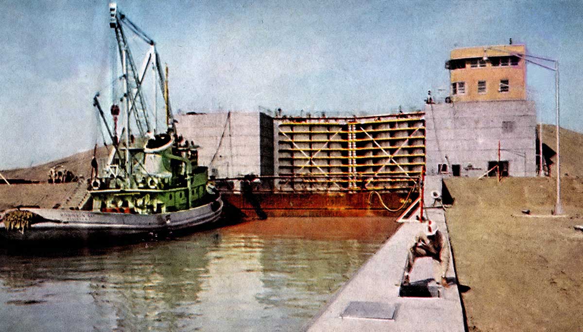
SHCMS037: Tug ROBINSON BAY Waits for the Snell Lock to Open.
The tug ROBINSON BAY was built for the St. Lawrence Seaway Development Corp. in 1958. It is used to place aids to navigation along the American sectors of the Seaway from Cape Vincent, N.Y. to below the Snell Lock. The stop logs, which allow the canal to be dewatered, are still in place below the lock. The crane hanging over the tug is used to place and remove the stop logs.
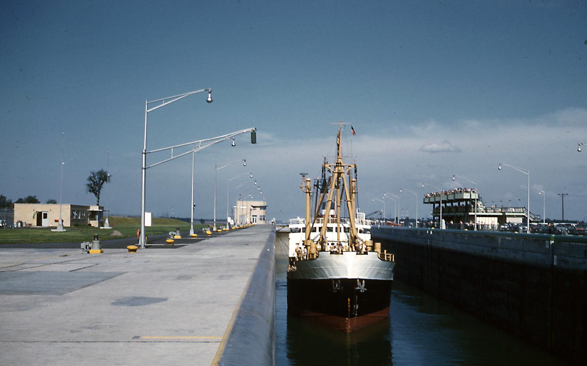
SHCMS037a: Snell Lock Opening Day, July 4, 1958.
Two canallers at the lower entrance to the Snell Lock on opening day, July 4, 1958. The river had been closed to shipping since July 1st, so that flooding above the Cornwall - Massena sector could take place. This pair are the first two ships to pass through the new locks and canals.
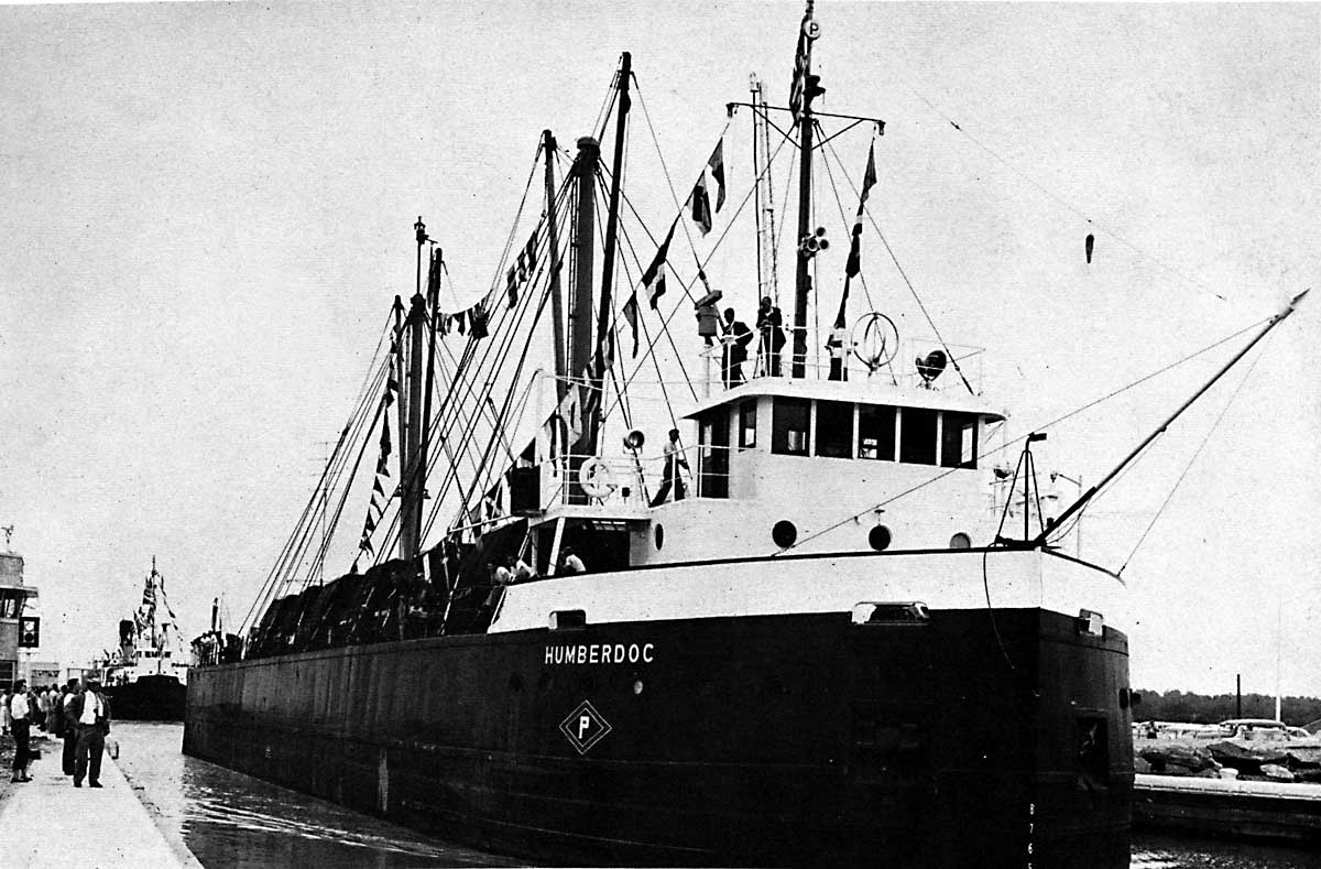
SHCMS037b: Snell Lock Opening Day First Ships, July 4, 1958.
The HUMBERDOC, followed by the MANITOULIN, are in the raised position in the Snell Lock. In the old canals these ships would have passed up through five lift locks to get to this level. The HUMBERDOC is carrying a load of paper in rolls. The MANITOULIN is loaded with pulpwood logs for the paper mill in Thorold.
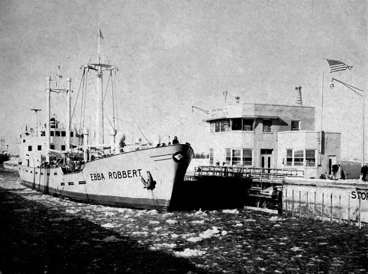
SHCMS038: The 'Salty' EBBA ROBERT Entering the Snell Lock.
On December 6, 1958, the EBBA ROBERT and another foreign flag ship passed down bound through the Snell lock. They were the last two overseas ships to pass through the lock that year.
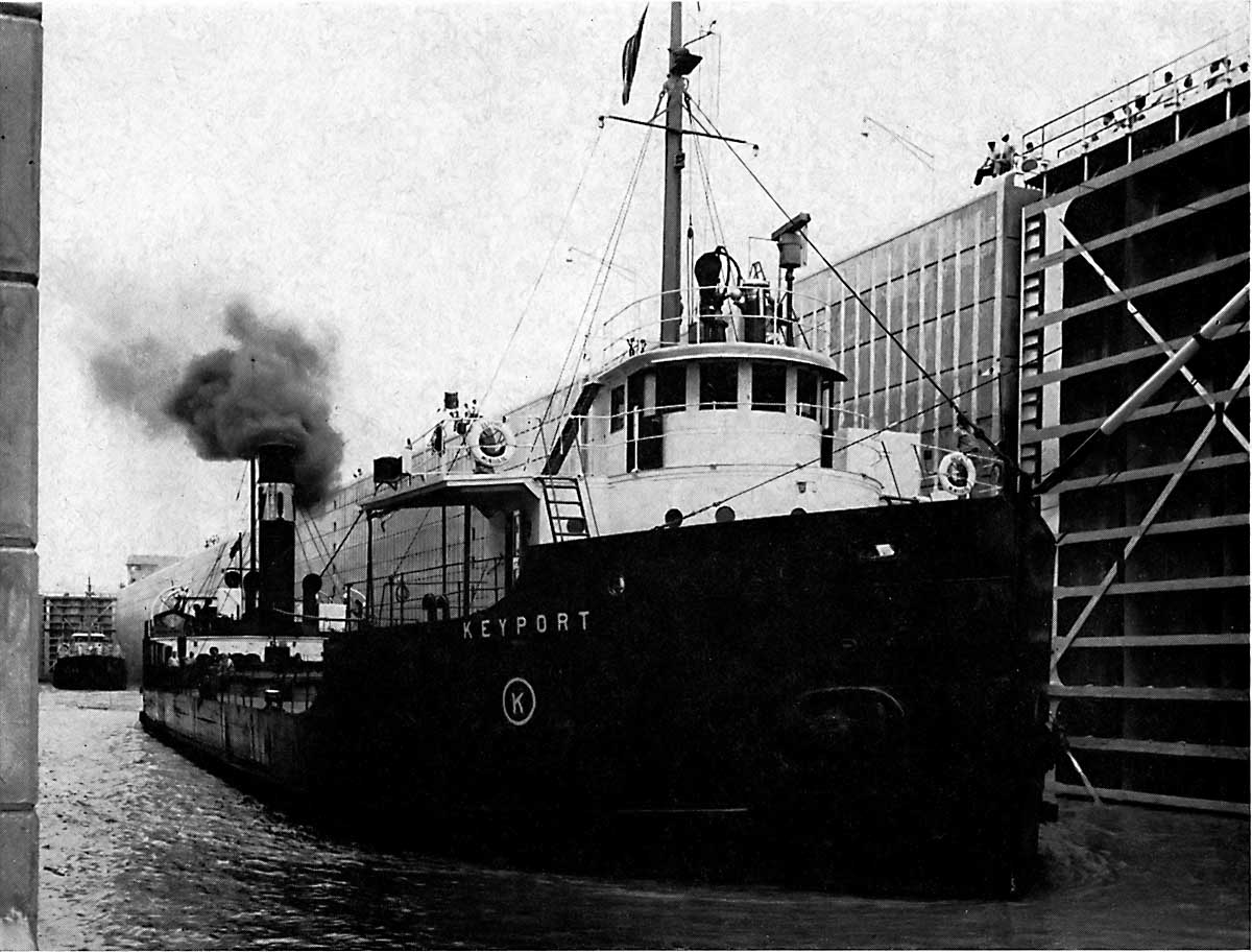
SHCMS038A: Canaller KEYPORT Departing Snell Lock.
The steamship KEYPORT was built to fit the old canals in 1909. Now that the Seaway is open, her days are numbered. She was sold for scrap in 1963.
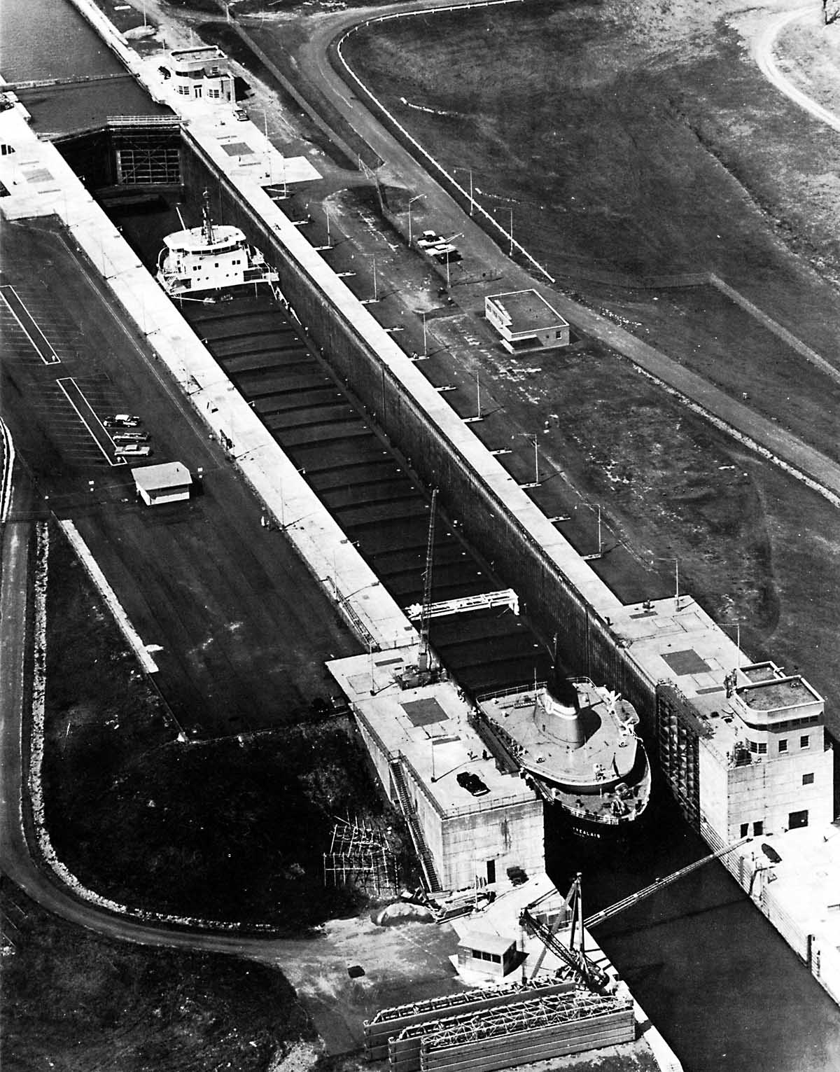
SHCMS039: MONTREALAIS Entering Snell Lock.
By comparison to the previous photo of an old canaller in the Snell Lock, the laker MONTREALAIS was built to maximum allowable dimensions for the new Seaway, 730' long and 75' wide. She is up bound and the upper sill below the upper gate can be seen. This ship will be raised at least 43 feet as the lock is filled from the pool of water above it.
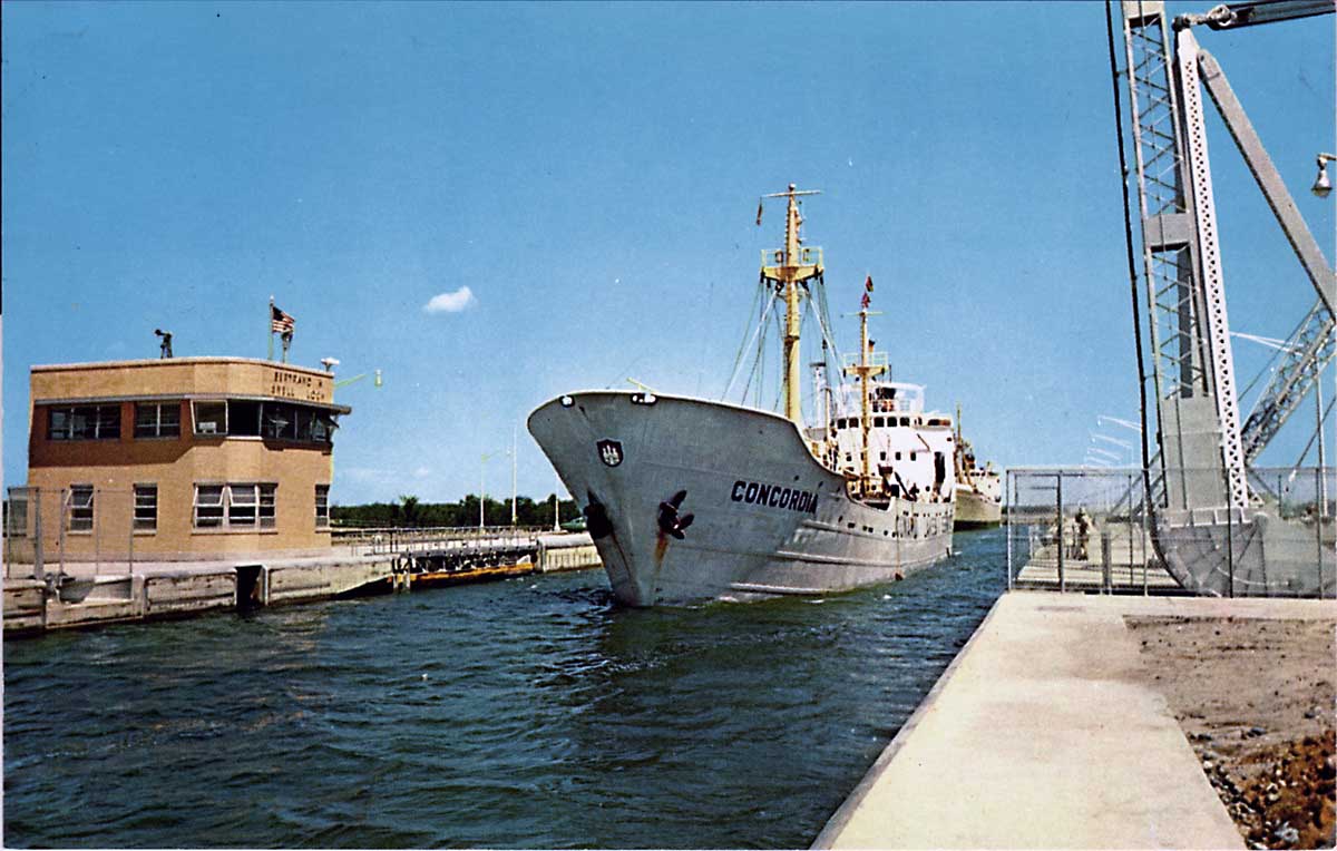
SHCMS040: MV CONCORDIA Departing Snell Lock Up Bound.
The German flag motor vessel CONCORDIA was built in 1953 and served in the Europe to Great Lakes trade from 1954 until 1960. She is 243' long and only 36' wide which was handy for the old canals but seems dwarfed by the big Seaway locks.
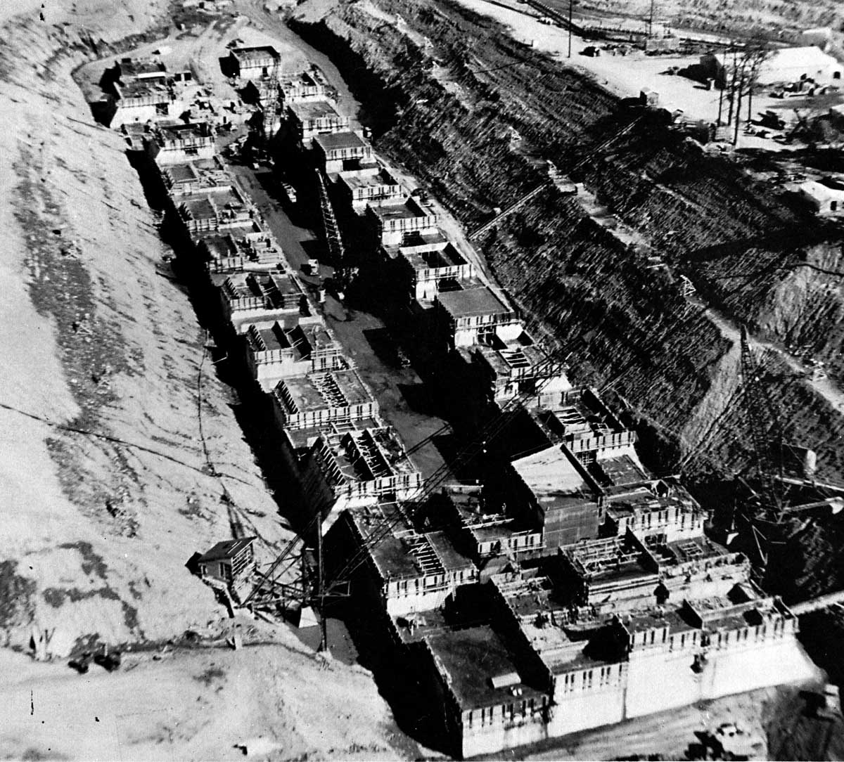
SHCMS041: EISENHOWER Lock Concrete Forms in Place 1956.
The first concrete was poured into the forms at the site of the new Eisenhower lift lock on July 11, 1956. In this aerial view, we are looking east. At the west end, the upper sill of the lock is already much higher than the east end.
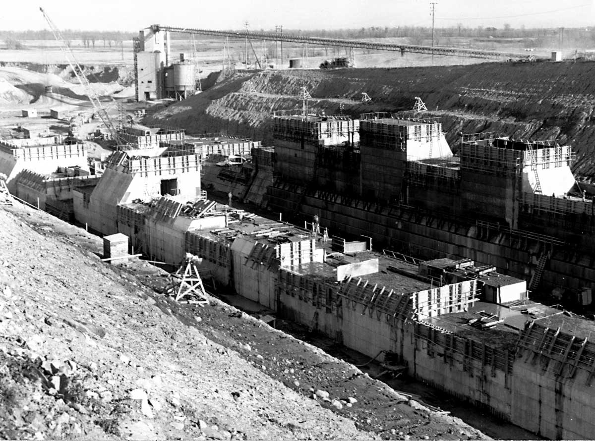
SHCMS042: EISENHOWER Lock, East End and Concrete Mixing Plant.
This view would have been taken later on in 1956 and we can see the forms are much higher than in the previous scene. In the background can be seen the concrete mixing plant that fed fresh concrete into these forms. 535,000 cubic yards of concrete were needed to complete this structure.
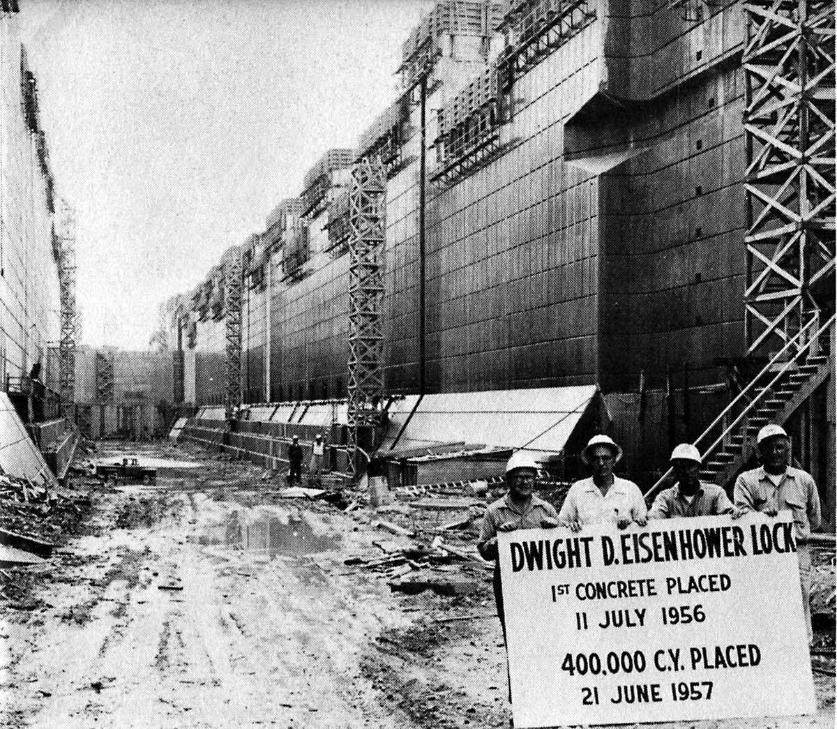
SHCMS042a1: Eisenhower Lock Construction Crew Celebrate a Milestone.
The foremen pose for a photograph while the work goes on behind them. They have a right to be proud as they did manage to stay on schedule and have the lock ready on the exact day as planned.
.jpg)
SHCMS042A: Miter Gate Partially Assembled in Eisenhower Lock.
This view of the inside of the Eisenhower Lock shows a partially assembled miter gate mounted in the recess. The sill upon which it will travel runs across the lock below the gate.
SHCMS042c: Eisenhower Lock 1958.
An aerial view of Eisenhower Lock looking east. The Wiley - Dondero Ship Canal leading down to Snell Lock can be seen in the background. Shortly after this photo was taken the roadway across the entrance to the lock was removed and the flooding took place.
SHCMS043: EISENHOWER Lock Ready for Flooding.
The Eisenhower Lock ready for flooding with water in the summer of 1958. Note the stop logs are still in place at the lower entrance to the lock. The Wiley-Dondero ship canal below the lock is partially filled with water while the Long Sault Canal above the lock is still dry. It will be filled during the formation of Lake St. Lawrence early in July, 1958.
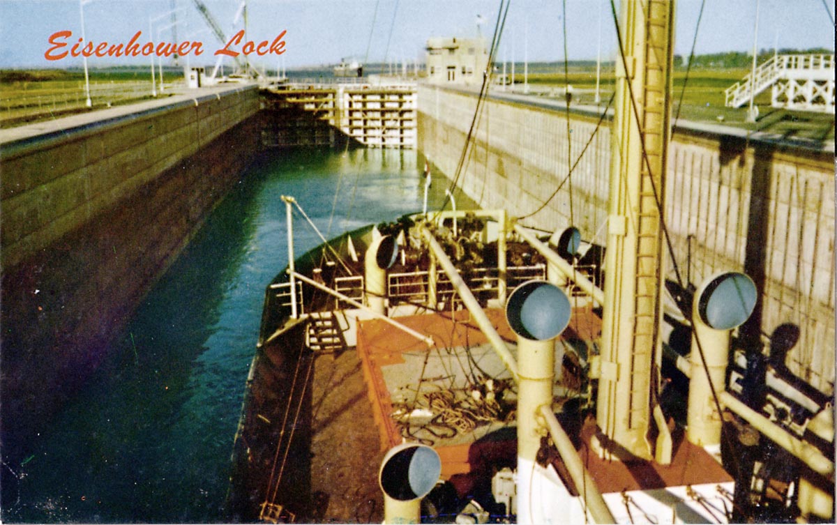
SHCMS044: Two Canallers In Eisenhower Lock.
Two old steam canallers, a Paterson fleet to the left and a Misener Steamships leading the way, enter Eisenhower Lock. Built in the 1920's, they have served their purpose and are now very close to being obsolete due to the opening of the Seaway. Both ships were retired and sold for scrap within a few years after this photo was taken, probably in 1958.
SHCMS044A: A Lone CSL Canaller in Eisenhower Lock.
A Canada Steamships Line steam package freight canaller rides high in the Eisenhower Lock. In the background can be seen the Barnhart Island Control Dam which regulates water level in Lake St. Lawrence.
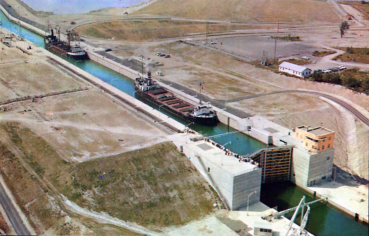
SHCMS045: Two Old Canallers Raised Up inside the Eisenhower Lock.
This is a close up look at the upper gates of the Eisenhower Lock. Inside the lock are two canallers. It was said that after the Seaway opened in 1958, each time an upper laker went down the river, an old canaller was withdrawn from service. That statement was not too far from the truth, as the old steam canallers went for scrap in droves in the late 1950's and early 60's. However, there were a number of newer diesel powered canallers that carried on for many years afterwards.
SHCMS045A: SUNGATE Passing Over the Tunnel Under the Eisenhower Lock.
The motorvessel SUNGATE, in Saguenay Shipping Ltd. company colours, sails over the tunnel that runs beneath the Eisenhower Lock. Saguenay Shipping was a Montreal based shipping company.
SHCMS046: Ship in Eisenhower Lock.
An ocean liner is being raised in the Eisenhower Lock. The high level water mark can be seen on the inside wall of the lock. The lift is about 42 feet.
SHCMS046a: JOLIETTE in Eisenhower Lock.
The French flag ship JOLIETTE is being raised in Eisenhower Lock. The visitor's center is on the right. The visitors have a great view of the ships in the lock here.
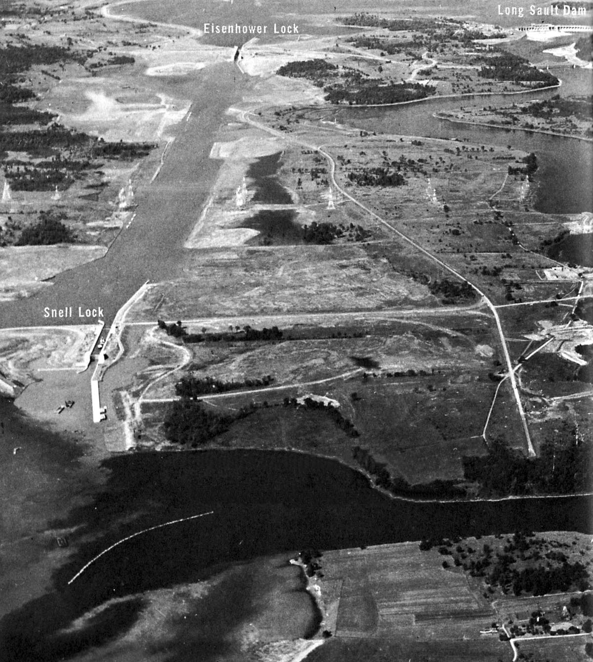
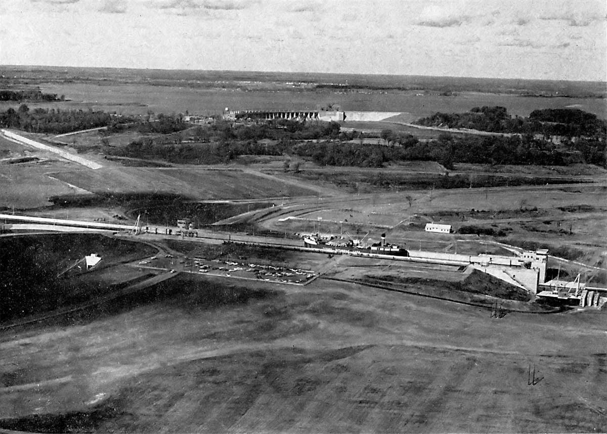
SHCMS046b: Snell & Eisenhower Locks 1958.
This aerial view shows the entire U.S. sector canal and locks system including the Snell Lock, the Wiley-Dondero Ship Canal between the two locks, and the Eisenhower Lock.
At the top right the Barnhart Island Control Dam can be seen. The curved white line in the river below Snell Lock is a dike built to divert the strong current running through the channel from right to left. This current caused many ships to lose control and strike the lower approach wall below the Snell Lock.
SHCMS047: Eisenhower Lock Looking East.
Two canallers have just been lowered in Eisenhower Lock and the first one is working its way out of the lock into what is commonly known as "The Pool" between the two lift locks. An up bound ship is slowly approaching the lower wall of the Eisenhower Lock.
SHCMS048: Eisenhower lock looking down the Wiley-Dondero ship canal.
An aerial view of the Eisenhower Lock with the Wiley-Dondero Ship Canal leading down to the Snell Lock below. The foreign flag ship in the foreground will tie up at the wall to the left and wait for the up bound ship to clear the lock. There is a ship lowered in the lock and when it sails out into the ship canal the ship waiting below the lock will get her turn to enter the lock. There are thousands of transits like this each year.
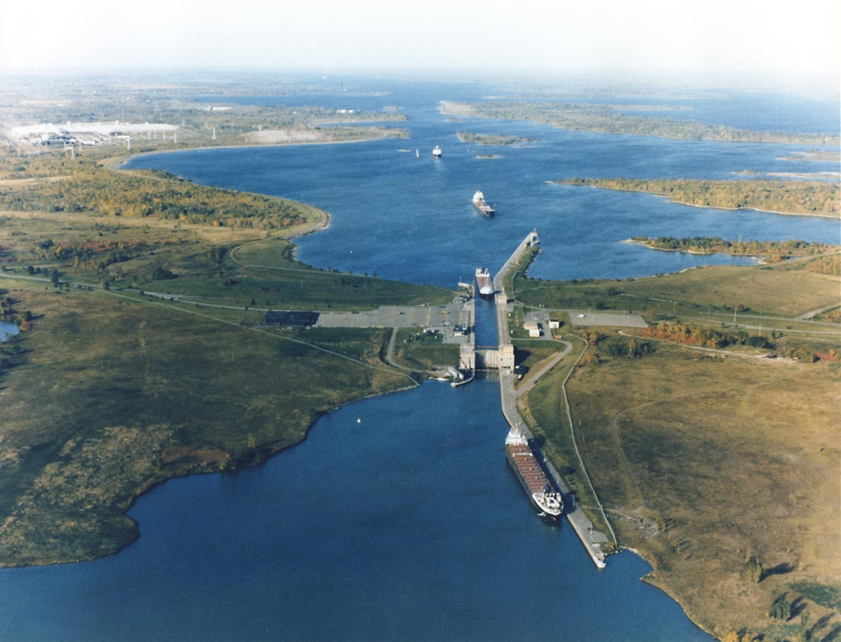
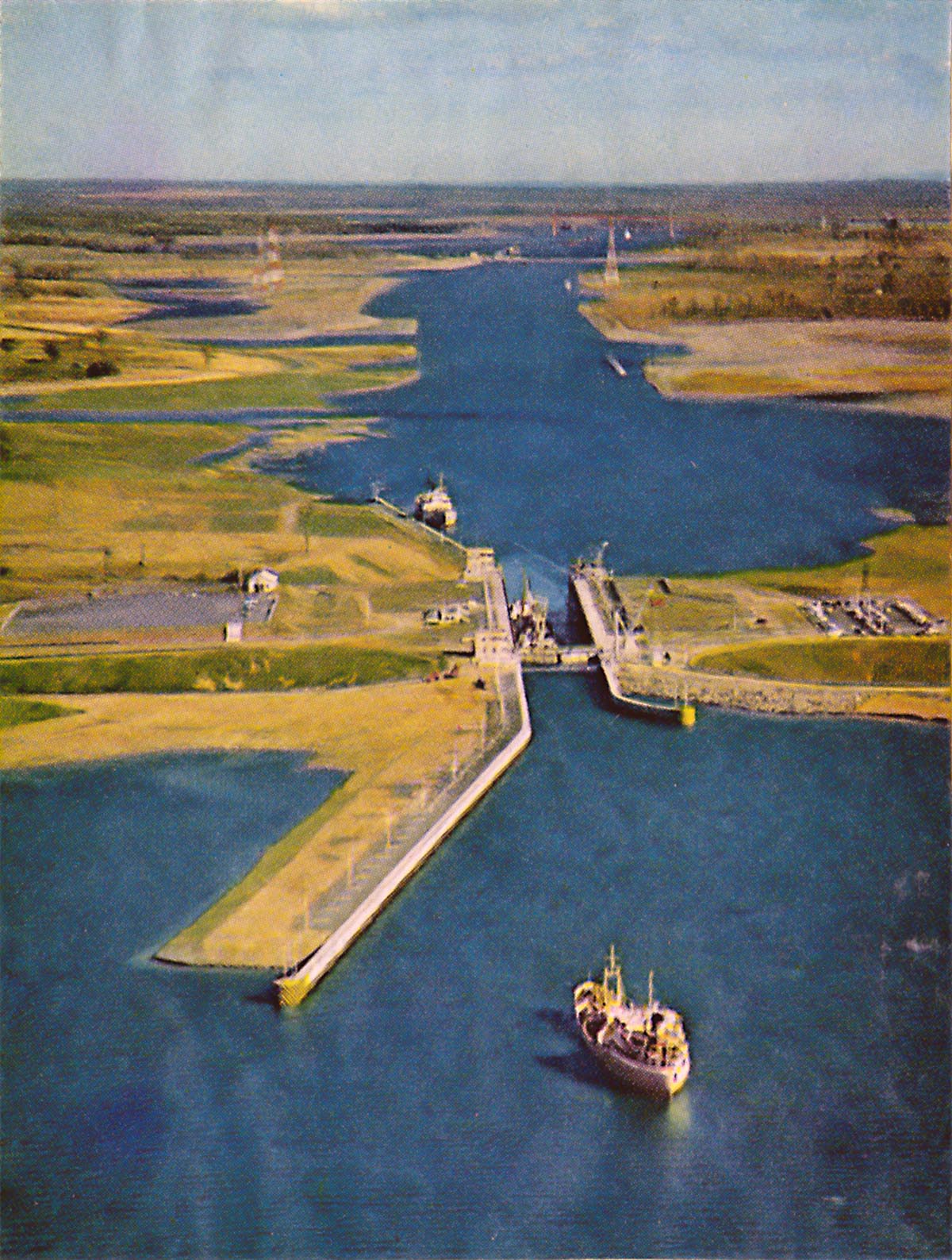
SHCMS049: Eisenhower Lock and the Long Sault Ship Channel.
An aerial view of the Eisenhower Lock with the Long Sault Ship Channel in the background. There are four ships in view here. A salt water ship has departed the lock up bound and her place is being taken by a down bound laker. Another laker waits below the lock and a down bound self unloader type laker is approaching the upper tie wall.
The Long Sault Ship Channel was man made and cut through the mainland and Long Sault Island. A series of dikes were built along the shoreline to the left to prevent further flooding of the mainland when Lake St. Lawrence was formed. The lake can be seen at the top of this image.
SHCMS053: A cut on the U.S. mainland east of Hutchins Bay.
Stripping the earth away to form a channel leading to the Eisenhower Lock. This scene is a few miles west of the entrance to the Eisenhower Lock. It is part of the Long Sault Canal, which must be 442 feet wide at the bottom and 550 feet wide at the surface of the water. The depth will be 27 feet when flooded.
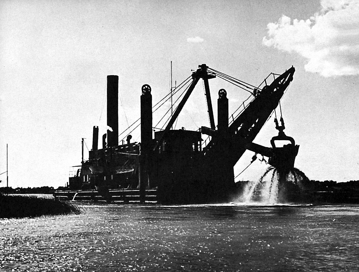
SHCMS053A: A steam powered bucket dredge at work cutting a channel.
This is a typical steam dredge of the era after WWII. The material cut from the bottom of the river was loaded onto dump scows that, when loaded, were towed to designated spoil areas to be dropped back to the bottom of the river.
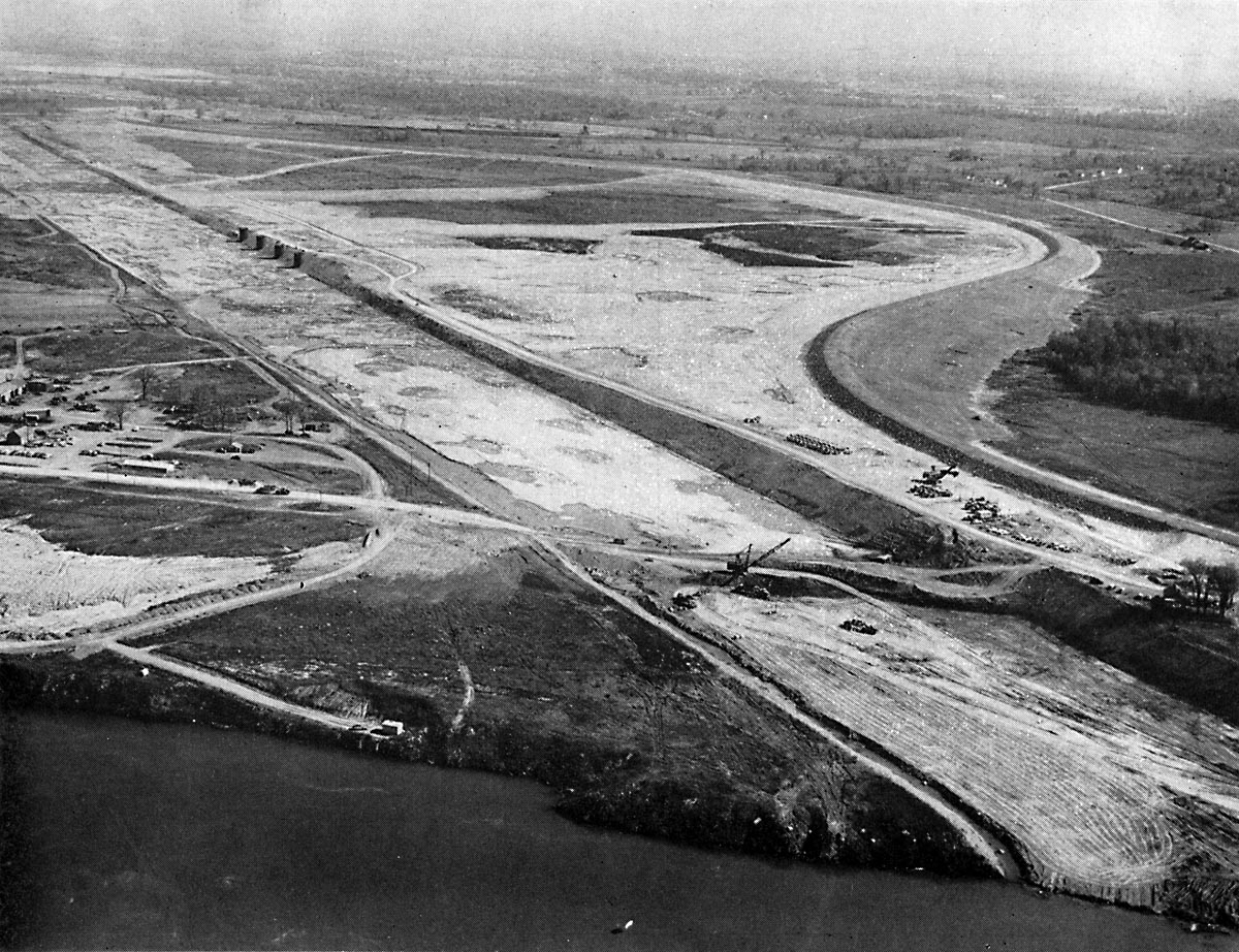
SHCMS054: An aerial view of the Long Sault Canal looking east.
The work of cutting the Long Sault Canal through the mainland of New York State is nearly complete in this view. In the background curving away into the distance is the new dike built from material cut from the new canal. The total length of the Long Sault Canal is 10 miles. Note the four dark shapes to the left of center. These appear to be small towers but actually are steel walled mooring cells to be used by ships if needed to tie up. Look for these same mooring cells in SHCMS055.
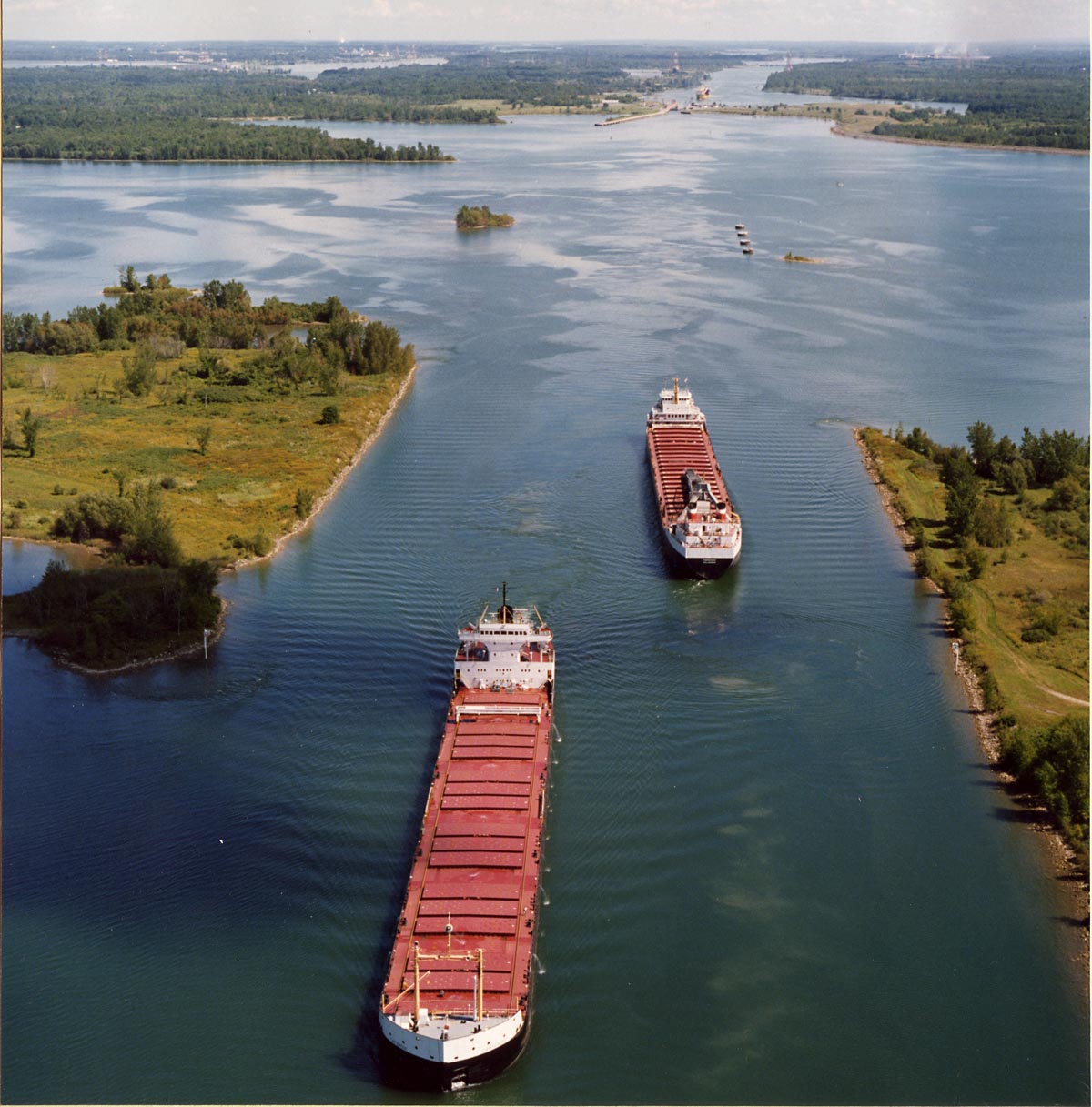
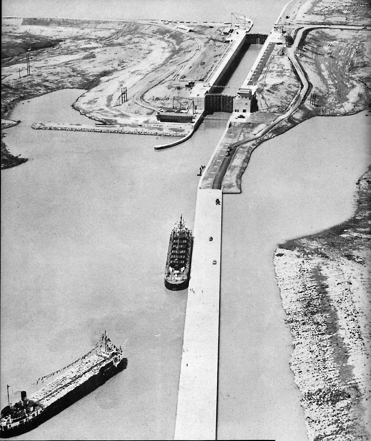
SHCMS055: Two ships passing in the Long Sault Canal after flooding.
This aerial view is looking straight down the Long Sault Canal towards the Eisenhower and Snell Locks. This channel was officially renamed the Wiley - Dondero Ship Canal when it opened. The mooring cells, seen to the upper right of the ships, were viewed in SHCMS054 before Lake St. Lawrence was formed.
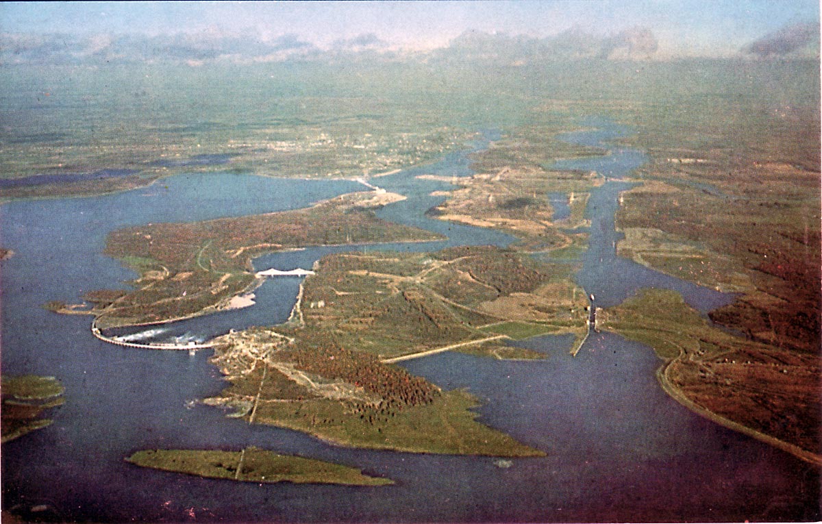
SHCMS056: An aerial view of the entire Cornwall - Massena Seaway and Power Dam complex.
In the upper left area can be seen the city of Cornwall with the Moses - Saunders Power Dam just below to the left. A new bridge to Barnhart Island spans the channel running below the control dam. To the right is the Eisenhower Lock with the Wiley - Dondero Ship Canal running down to the Snell Lock.